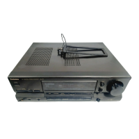
SA-EX310
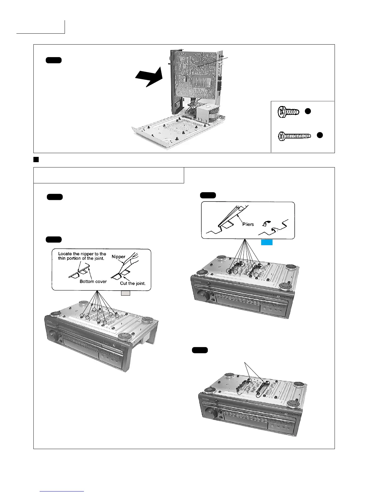
Step 8
Connect the front panel to
the main P.C.B. as shown.
[XTB3+20JFZ] (Black)
f
[XTB3+8FFZ] (Black)
e
MAIN P.C.B. (Solder Side)
Check the Main P.C.B. as shown
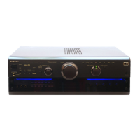
Main Component Replacement Procedures
Step 1
Remove the top cabinet.
Step 2 Cut the joints as shown below. (6 joints)
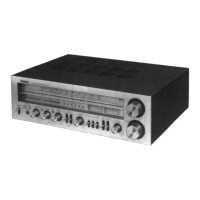
Step 4
Desolder the terminals of Power IC and
Regulator Transistor.
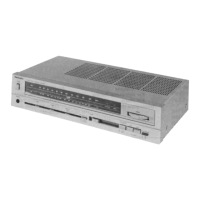
Step 3 Fold the joints. (6 joints)
1. Replacement of the Power IC and
Regulator Transistor