EasyManuals Logo

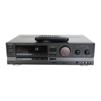
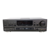
Technics SA-GX230 Service Manual

Technics SA-GX230
20 pages
To Next Page IconTo Next Page
To Previous Page IconTo Previous Page
Page #11 background imageLoading...
Page #11 background image
|
SA-GX230
|
м
SCHEMATIC
DIAGRAM
(
schematic
diagram
may
be
modifled
at
any
time
)
with
the
development
of
new
technology.
(Parts
list
on
pages
40—44.)
|
1
И
"a
кт
р
Ios
р
y.
1
ЖЕЛКИ
o
Note
1:
,
,
r
Note
2:
|
5501
:
Speaker
selectors
(SPEAKERS)
switches.
*
Use
of
ceramic
filters
in
pairs
А
[5601-1:
A,
5601-2:
В)
mE
|
|
The
ceramic
filters
(CF201,
CF202)
for
FM-IF
circult
5701
:
Voltage
selector
(VOLT
ADJ)
switch.
_
^
|
are
available
in
three
ranks.
For
this
circuit,
be
sure
For
(E,
EB)
areas.
e
|
to
use
the
ceramics
of
the
same
rank
in
a
pair.
8901—910
:
Preset-tuning
(1-0)
(30
CHANNEL
RANDOM
At
repairing
and
replacement,
pay
close
attention
to
PRESET
TUNING)
switches.
|
|
р
the
short
jumpers
(J221,
J222)
for
use
as
different
|
S901:
1,
$902:
2,
5903:
3,
$904:
4,
oo
short
jumpers
must
be
used
depending
on
each.
rank
|
S905:
5,
5906:
6,
5907:7,5908:
|
of
the
ceramic
filters.
$909:
9,
$910:0
|
re
КИ
5914
:
Power
(POWER)
switch.
1,"
|
Color
marking:
*8916—918,
.
'
ЖО
|...
|
(Blue,
921—923
:
Input
selector
switches.
`
d.
SL
Ei
!
B
S916:
PHONO,
$917:
TUNER;
ч
`
cus
ТЕ:
|
5918:
TAPE,
S921:
VCR
2,
|
jun
5
S922:
VCR
1,
$923:
CD
PET
\
TUNER
circuit
For
(EG)
area.
*
5925
ч
ES
ӘНЕ
ng
5
rn
.
*
$929,
936
:
Tuning
(TUNING)
switches.
'
^
;
',
':
|
"n
"s
e
d
e
pA
AL
M
e
AE
IE
E
FM
EEI
UMTOO!
0201,202
0204
AF
SIGNAL
(Len)
,
.,(8929:
DOWN,
$936:
UP)
5^.
^
JEN
*.
Note:
О
mark:
short
jumper
is
used.
ә
23095,
„p
2352668
|
wis
Se
Си
emeouence
dag
inda
us
м
cee
po
MIS
5930,
931,
:
|
A
Е.
|
Е
NE.
do
nr
x
mark:
short
jumper
is
not
used.
m
P:
EET
Т,
Ber
88
ғо
ANT273A
,
m
C206
15р
ча,
к
1
932
:
Band
selector
switches.
жек.
sl
Fi
m
ig
5
Lo
үй.
que
М
ee
ae
Б
ezea
сез
аи
ВОН
|
)
2:M
or
(E,
areas.)
J
——
à
2s
ғ
$933
:
FM
mode
selector
(FM
MODE]
ewitch.
as
cs
E
C
s
5934
:
Memory
scan
(MEMORY
SCAN)
switch.
~.
|
|
5935
:
Memory
(MEMORY)
switch.
п
М
Signal
line
pu-
ИСА
ae
‘i
вас
:
FM
OSC
signal
-
.,
ЗЕ;
FM
signal»
шинаф
:
AM
(MW/LW)
OSC
signal
.
aamulp
:
АМ
(MW/LW)'signal
E
:
Phono
signal.
Е
s
1
AF,
signal
(Гой).
у
АМ
АМТ
&
(0
6
о
Д
ЕМ
OFFSET
o
m
:
Positive
voltage
lines
|
|
6!
|
|
VOLTAGE
(Оту)
жа
нини
на
:
Negative
voltage
lines:
y
Ow
uo
cft
vip
«diti
I^
—-
*
Important
safety
notice:
Я
Components
identified
ру
А
mark
have
special
|
|
D
characteristics
important
for
safety.
When
replacing
pe
any
of
these
components,
use
only
manufacturer's
...
"
Specified
parts.
Indicated
voltage
values
are
standard
values
for
the
unit
measured
by
the
DC
electronic
circuit
tester
(high-impedance)
with
the
chassis
taken
аз.
IK
2107
RIOS
B.
|
|
SHEER
=
T
Ex]
WK
560
=~
TH
|
сов,
г
Ja
T
wo,
mb
gal
galg
a
о
b
(>
ә
`
y
-04
n
n
:
{юв
ME
c
Vary
Ss
“ІІ
(^
)esei|
SSI
281
3212
bis
оэ
|
р
т
E
oan
05305
-0N
i
CP
x
-
у F
р
|
8.2
-04Y
E)
gans
oo
3
ою
Тее
ce
y
CFA
1
1
САМ1
1
|
р
|
iv
р
15V
І
F
||
Е.
З7.5ЫН:--ЮВЫНЕ
x
$30XHt-—1620XHr
`
|
x
2301302
standard.
Therefore,
there
may
exist
some
errors
in
the
AM
[EB]
LINE
оа
ил
T
EE
oram
2—14
ыы
to
nee
ee
voltage
values,
depending
on
internal
impedance
of
the
FM/AM
LOOP
FILTER
i
POWER
SUPPLY
CONT.
or
-L—L
——
A
DC
circuit
tester.
;
2SADSASQRSTA
21465
05ТА
ШІП
587
MUTING
CONT.
|
z
Lie
ly
*
All
voltage
values
shown
in
circuitry
are
DC
voltage
in
ешн
зеам
DIT
e
9000909
006960709000
FM
signal
(Stereo
signal)
reception
made.
755285
222555:
*
Figures
in
(
)
Stand
for
DC-voltage
in
AM
(MW)
signal
2%
TR
ic
M
reception
mode.
|
|
|
E
ey
то
млн
circuit
*Figures
їп
С
1
Stand
for
DC-voltage
in
LW
signal
To
Muar
елат
ae
pass
as
reception
mode.
TE
e
The
supply
part
number
is
described
alone
in
the
replacement
parts
list.
|
Production
Part
No.
|
Supply
Part
No.
IC301
AN7470
SVIUPC1161C3
2891
ВСОНС-677-Е
АСОНС-677
*
Caution!
-IC
and
LSI
are
sensitive
to
static
electricity.
F
`
Secondary
trouble
can
be
prevented
by
taking
care
during
repair.
|
|
e
*
Cover
the
parts
boxes
made
of
plastics
with
alminum
|
foil.
4
|
x
Ground
the
soldering
iron.
|
*
Put
a
conductive
mat
on
the
work
table.
0
*
Do
not
touch
the
legs
of
IC
or
LSI
with
the
fingers
|
directly.
.
ка
cM,
E

Questions and Answers:

Question and Answer IconNeed help?

Do you have a question about the Technics SA-GX230 and is the answer not in the manual?

Technics SA-GX230 Specifications

General IconGeneral
BrandTechnics
ModelSA-GX230
CategoryStereo Receiver
LanguageEnglish

Related product manuals