m
CONTENTS
Page
BEFORE
REPAIR
AND
ADJUSTMENT
.....0.
2
SGHEMATIG
DIAGRAM.
siscssvescsscseseseentecesicccecnseeecsecs
PROTECTION
CIRGUIGRY
cncssccosnseosscsescceaceesseneacsee
2
WIRING
CONNECTION
DIAGRAM
ACCESSORIES
wiccsisssonsconexesssesies
ie
BILAOCK
DIAGRAM)
ci
ceiccsecccascseseesescenecessceectecnses
LOCATION
OF
CONTROLS
........
8
MEASUREMENTS
AND
ADJUSTMENTS
DISASSEMBLY
INSTRUCTIONS
.....
eee
4~6
EXPLODED
VIEW
iosc-ssssesssscracesccccrenssaeenenesnansenese
PRINTED
CIRCUIT
BOARDS:
«..:...-0.-cc-ssc01c.seseases
00
7~
10
REPLACEMENT
PARTS
LIST
ou...
eeeeeeeeeeeeeeeeee
aa
TERMINAL
GUIDE
OF
RESISTORS
AND
CAPACITORS
...........ceeesceeeeeeeeeee
TRANSISTORS,DIODES
AND
IC’S
ooo.
10
m=
BEFORE
REPAIR
AND
ADJUSTMENT
(1)
Turn
off
the
power
supply.
Using
a
109,
10W
resistor,
shortcircuit
both
ends
of
power
supply
capacitors
(C609,C610)in
order
to
discharge
the
voltage.
(2)
Before
turning
on
the
power
switch
of
the
unit.
A.
Connect
the
voltage
controller
to
the
primary
side.
B.
Connect
the
AC
ampere
meter
to
the
primary
side
or
connect
the
DC
voltage
meter
to
the
”+B”
circuit
of
the
secondary
side.
C.
Turn
the
VR
of
I[CQ(VR401,VR402,VR551
and
VR552)toe
minimum(counterclockwise).
D.
After
setting
the
output
to
zero
of
the
voliage
contolier,turn
on
the
power
switch
of
the
unit.
And
increase
ihe
output
of
voltage
controlier
gradually.
Then,
check
carefully
whether
the
current
vaiue
of
primary
side
become
more
than
following
value
or
whether
the
DC
voltage
of
secondary
side
is
increasing
slowly.
E.
If
the
value
of
current
is
increasing
unusually
or
the
DC
voltage
is
not
increasing,lower
the
output
level
of
voltage
contoller
immediately.
@
The
current
value
of
the
primary
side
at
no
signal.
(Confirm
the
power
supply
voltage
of
each
area
and
provided
voltage
of
the
unit.)
Power
supply
voltage
AC110V
AC127V
AC220V
AC240V
Consumed
current
50/60Hz
400
~
850mA
390
~
840mA
200
~
450mA
180
~
480mA
m
PROTECTION
CIRCUITRY
The
protection
circuitry
of
the
amplifier
may
have
If
this
occurs,
follow
the
procedure
outlined
below:
operated
if
either
of
the
following
conditions
is
noticed:
1.Turn
off
the
power.
@
No
sound
is
heard
when
the
power
is
turned
on.
2.Determine
the
cause
of
the
problem
and
correct
it.
@
Sound
stops
during
a
performance.
3.Turn
on
the
power
once
again.
The
function
of
this
circuitry
is
to
prevent
circuitry
damage
if,
for
example,
the
positive
and
negative
speaker
Note:
connection
wires
are
“shorted”
,
or
if
speaker
systems
with
When
the
protection
circuitry
functions,
the
unit
will
not
an
impedance
less
than
the
indicated
rated
impedance
operate
unless
the
power
is
first
turned
off
and
then
of
the
amplifier
are
used.
on
again.
m
ACCESSORIES
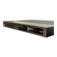
@
Stereo
CONNESCION
CADIS
siicssecccs
ctcacccesvevencesneatedsccvewsteeseceenentenese
1
(SFDACO5E03)
for
[E],
[EG],
[El],
[EH],
[EB]
and
[EF]
areas.
For
United
Kingdom
and
some
areas,the
power
cord
is
directly
attached
to
the
unit.
Configuration
of
AC
power
supply
cord
differs
according
to
area.
-2-