Do you have a question about the Technics SH-DJ1200 and is the answer not in the manual?
Details input sensitivity and impedance for various connections.
Specifies output voltage levels for different outputs.
Indicates maximum output voltage without headphones.
Lists impedance requirements for different output types.
Outlines the frequency range for different audio inputs.
Specifies the acceptable level of background noise.
Describes the dB/oct slope for tone controls.
Covers power supply, consumption, dimensions, and weight.
Procedure to test electrical insulation for safety compliance.
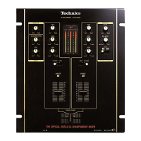
Describes the user-friendly design and panel layout for optimal operation.
Details the main audio processing and control features of the mixer.
Explains the build quality and materials used in the mixer's construction.
Background information about the DJ organization sponsoring championships.
Illustrates how to connect external equipment to the mixer's rear panel.
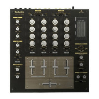
Identifies the main volume control knob.
Identifies the AUX/EFFECTOR volume control.
Identifies the microphone volume control.
Identifies the low-range EQ control for CH A/B.
Identifies the input selector for CH A/B.
Identifies the input level control for CH A/B.
Identifies the high-range EQ control for CH A/B.
Identifies the input sensitivity trim control for CH A/B.
Identifies the meter indicating output levels.
Identifies the monitor volume control.
Identifies the monitor balance control.
Identifies the headphone monitor selector.
Identifies the cross fader control.
Identifies the microphone input jack.
Identifies the headphone output jack.
Identifies the power on/off button.
Identifies the AC power input socket.
Identifies the CH A/B line input connector.
Identifies the CH A/B phono input connector.
Identifies the phono ground terminal.
Identifies the line output connector.
Identifies the monitor output connector.
Identifies the auxiliary input connector.
Identifies the recording output connector.
Explains how to adjust balance between audio sources for monitoring.
Details the function and connection of the monitor output for external speakers.
Procedures for checking the operation of major printed circuit boards.
Step-by-step guide for safely removing PCBs from the unit.
Instructions on properly routing and securing internal wiring during assembly.
Explains symbols and component notations used in the schematic diagrams.
Advises on handling electronic components and preventing static discharge.
Layout diagram for the Input A circuit board.
Layout diagram for the Input B circuit board.
Layout diagram for the Output circuit board.
Layout diagram for the Monitor circuit board.
Layout diagram for the Cue Switch circuit board.
Layout diagram for the Input Select A Switch PCB.
Layout diagram for the Input Select B Switch PCB.
Layout diagram for the Tone Control A circuit board.
Layout diagram for the Tone Control B circuit board.
Layout diagram for the Transformer circuit board.
Layout diagram for the Power Switch circuit board.
Layout diagram for the LED circuit board.
Layout diagram for the Microphone circuit board.
Layout diagram for the Headphones circuit board.
Layout diagram for the spare Channel Fader circuit board.
Layout diagram for the spare Cross Fader circuit board.
Layout diagram for the Channel Fader A circuit board.
Layout diagram for the Cross Fader circuit board.
Layout diagram for the Channel Fader B circuit board.
Lists integrated circuits and their part numbers.
Lists transistors and their part numbers.
Lists diodes and their part numbers.
Lists resistors and their part numbers.
Lists connectors and their part numbers.
Lists variable resistors and their part numbers.
Lists various cables and their part numbers.
Lists jacks and their part numbers.
Lists hardware components like screws, nuts, and washers.
Lists cabinet parts, covers, knobs, and brackets.
Lists the materials used for packaging the unit and its accessories.
Lists the accessories that are supplied with the product.
| Channels | 2 |
|---|---|
| Frequency Response | 20 Hz - 20 kHz |
| Input Connectors | RCA |
| Crossfader | Yes |
| Inputs | 2 |
| EQ | 3-band |
| Power Supply | AC 100-240V |
| Type | Digital DJ Mixer |
| Output Connectors | RCA (Master Out, Booth Out), 1/4" (Headphone Out) |