EasyManua.ls Logo

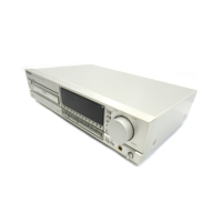
Technics SL-PG200A

Technics SL-PG200A
34 pages
To Next Page IconTo Next Page
To Previous Page IconTo Previous Page
Loading...
SL-PG200A
Mi
TERMINAL
FUNCTIONOF
IC’S
¢
1C6501
(482220973234/T
DA8808T):
Photo
diode
signal
processor
F
ue
Function
Mark
fo
Function
Division
i
Division
Gain
control
input
of
HF
Current
output
of
normalized,
amplifier.
A
FE
e
switched
focus
error
signal
GCHF
I
gna
Current
output
from
HF
amplitude
detector
Current
output
of
switched
focus
Vp
jl
Positive
supply
voltage
FElag
error
signal,
intended
for
lag
network
HF
amplifier
and
equalizer
HFout
ie)
voltage
output
Laser
amplifier
current
output
DET
I
HF
detector
voltage
input
:
a
Laser
monitor
diode
input
Sc
I
Starting
up
capacitor
input
On/off
control
(start
input);
Gain
control
input
for
AC
and
LF
Si/RD
ke)
ready
signal
output
(starting
up
amplifiers.
Current
output
from
procedure
successful)
|
LF
amplitude
detector
Equalizer
reference
current
input
Summation
of
amplified
currents
DC
and
LF
gain
control
reference
from
D3
and
D4
current
input
oy
a
Summation
of
amplified
currents
Focus
normalizing
circuit
from
D1
and
D2
starting
current
PLL
on
hold
output
Current
inputs
to
DC
and
LF
photo
diode
amplifier
Track
loss
output
Current
inputs
to
DC
and
LF
Drop
out
detector
suppression
: :
|
li
hoto
diode
amplifier
input
+
Negative
supply
connection
for
i
Current
input
to
HF
amplifier
FE
and
FElag
output
stage;
also
substrate
connection
Ground
connection
of
device
Low
pass
filter
for
Iret,
used
in
track
loss
(TL)
detector
and
LF
Decoupling
input
gain
control
(internal
bypass)
*
1C6503
(482220973235/TDA8809T):
Radial
error
signal
processor
Function
Mark
U0
Function
No.
|
|
Division
|
Positive
supply
voltage
al
Connection
of
integrator
18
Lag
capacitor
for
(Re1—Re2)
input
currents
Frequency
setting
capacitors
for
oscillator
[
pu
generator
input
19
Lead
o
|
Lead
output
Biassing
resistor
for
oscillator
20
Vref
|
Internal
reference
voltage
output
frequency
and
internal
Se
amplitude
24
AGC
Radial
error
digital
signal
+
devided
by
four
“|
Biassing
resistor
for
current
22
oO
output
for
track
jumping
(3/2
bits)
Gain
control
input
for
radial
error
signal
Digital
output
of
sign
(Re2—Re1)
Input
control
bits
for
off-,
catch-,
23
play-status
and
DAC
output
current
offset
in
offset
1
|
iF
Offset
control
input
for
radial
Offset
control
output
for
radial
offset
24
|
offset
off
|
[Positive
external
voltage
input
-
Low-pass
filter
for
Re1
and
Re2,
used
for
radial
offset
control
Negative
external
voltage
input
25
CLPF
(also
substrate
connection)
|
GND
terminal
26
CHPF
a
Current
output
of
amplified
(Re2—Re1)
input
currents
Input
for
amplified
currents
from
photo
diodes
D1
and
D2
VHigh-pass
filter
for
Re1
and
Re2,
4
used
for
radial
offset
control
Radial
error
input
Voltage
output
of
integrated
Input
for
amplified
currents
from
(Re2—Re1)
input
currents
photo
diodes
D3
and
D4

Related product manuals