"022/K
SU-S022/K
·
...
12
·
...
13
·
...
14
·
...
14
.15~16
·
...
17
·
...
17
·
...
17
·
...
18
2
~
1)
Jtlets
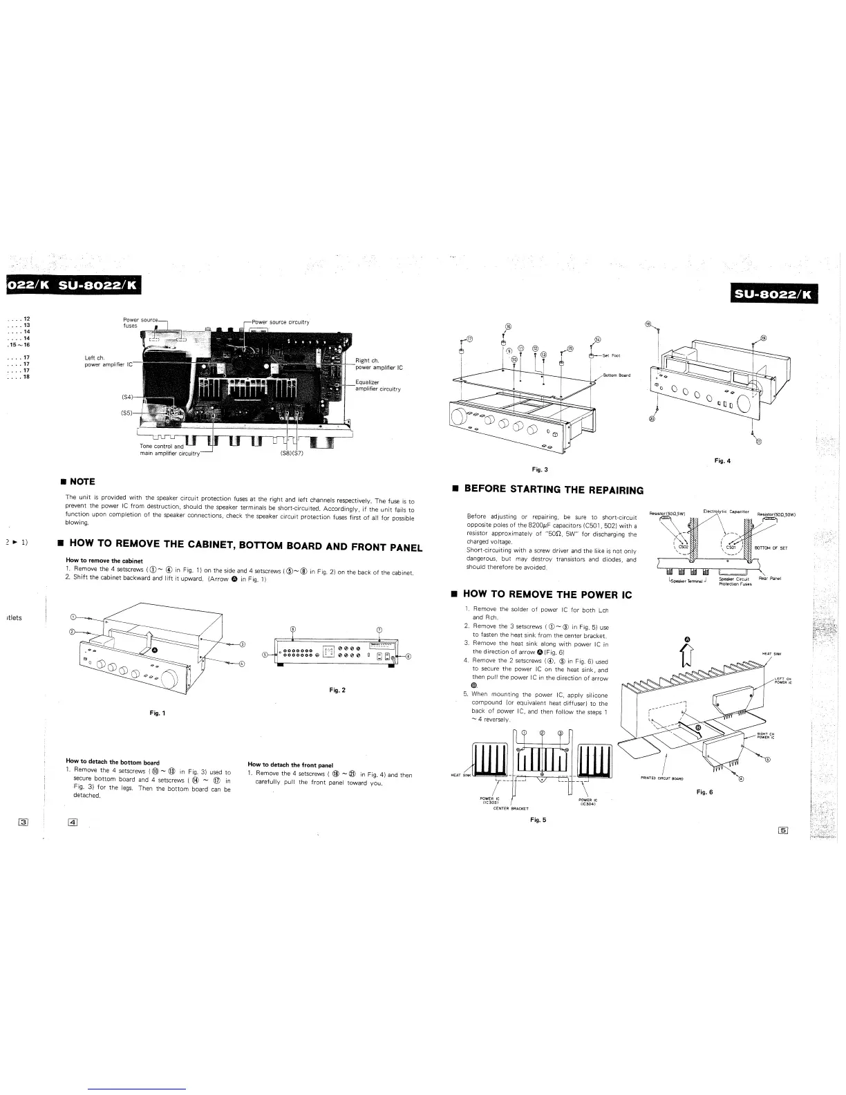
Left
ch.
power amplifier I
• NOTE
main Ctmplifier
ci
Right
ch.
power amplifier
le
Equalizer
amplifier circuitry
The
unit
is
provided
with
the speaker
circuit
protection
fuses at the right and
left
channels respectively. The fuse
is
to
prevent the power IC
from
destruction, should the speaker terminals
be
short-circuited.
Accordingly,
if
the
unit
fails
to
function
upon
completion
of
the speaker connections, check the speaker
circuit
protection
fuses
first
of
all
for
possible
blowing.
• HOW
TO
REMOVE THE CABINET, BOTTOM BOARD AND FRONT PANEL
How
to
remove the cabinet
1.
Remove the 4 setscrews
(CD
~
@ in Fig.
1)
on the side and 4 setscrews
(@~
® in Fig. 2) on the back
of
the cabinet.
2.
Shift
the
cabinet backward
and
lift
it
upward.
(Arrow
G in Fig.
1)
Fig. 1
How
to
detach the bottom board
1.
Remove the 4 setscrews
(@
~
@ in Fig. 3)
used
to
secure
bottom
board and 4 setscrews ( ®
~
@ in
Fig. 3)
for
the
legs.
Then the
bottom
board
can
be
detached.
Fig. 2
How
10
detach the front panel
1.
Remove the 4 setscrews ( @ - ® in Fig. 4)
and
then
carefully pull the
front
panel toward you.
~
y-®
T
~
~
(9)@
r®
,9
T
~set
Foot
@
~
Bottom Board
Fig. 3
• BEFORE STARTING THE REPAIRING
Before adjusting or repairing,
be
sure
to
short-circuit
opposite poles
of
the
8200pF
capacitors (C501, 502)
with
a
resistor
approximately
of
"50[2,
5W"
for
discharging the
charged voltage .
Short-circuiting
with
a screw driver and the like
is
not
only
dangerous, but may destroy transistors
and
diodes,
and
should therefore
be
avoided.
• HOW
TO
REMOVE THE POWER IC
1.
Remove the solder
of
power
IC
for
both
Lch
and Rch.
2. Remove the 3 setscrews
(CD
- ®
in
Fig.
5)
use
to
fasten the heat sink
from
the center bracket.
3.
Remove the heat sink along
with
power IC in
the
direction
of
arrow G (Fig.
6)
4.
Remove the 2 setscrews
(@,
CID
in Fig.
6)
used
to
secure the power
IC
on the heat sink,
and
then pull the power IC in
the
direction
of
arrow
@.
5.
When
mounting
the power IC,
apply
silicone
compound
(or equivalent heat diffuser)
to
the
back
of
power I
C,
and then
follow
the steps 1
- 4 reversely.
POWER
IC
IIC3031
CENTER BRACKET
Fig. 5
POWER
IC
IIC3041
SU-8022/K
~
19
i
Fig. 4
Electrolytic
Capacitor
Resistor(500,50W)
r=J
Lspeaker Tenniral J
Speaker Circuit
Rear
Panel
Protection Fuses
PRINTED
CIRCUIT
BOARD
Fig. 6
LEFT
CH
POWER le