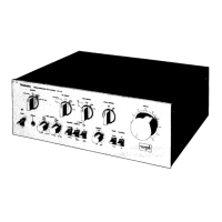
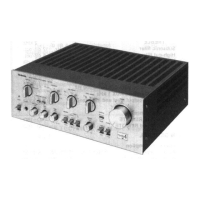
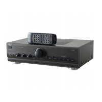
Do you have a question about the Technics SU-VX800 - SCHEMATICS and is the answer not in the manual?
Details continuous power output, harmonic distortion, damping factor, and impedance.
Covers input sensitivity, impedance, maximum input voltage, and tone control parameters.
Instructions for connecting CD players, turntables, tuners, and ground wires.
Guides for connecting tape decks, DAT, adaptors, and Extended Direct Drive sources.
Details on utilizing balanced and unbalanced audio signal connections.
Visual guide to test points and adjustment locations on the amplifier's circuit boards.
Procedure to set the idle voltage for the V-amp section.
Procedure to set the idle current for the I-amp section.
Steps to calibrate the audio signal gain across all channels.
Detailed circuit diagram for selecting audio input sources.
Circuit diagram illustrating connections for Tape 2/DAT functionality.
Schematic representing the primary amplifier circuitry and board layout.
| Frequency Response | 5Hz - 100kHz |
|---|---|
| Input Sensitivity | 150mV |
| Signal to Noise Ratio | 110dB |
| Dimensions | 430 x 160 x 360 mm |
| Power Output | 100 W + 100 W (8 ohms, 20 Hz - 20 kHz, 0.003% THD) |

