EasyManua.ls Logo

Technics SU-VX620 Service Manual

Technics SU-VX620
21 pages
To Next Page IconTo Next Page
Page #1 background imageLoading...
Page #1 background image
U-VX620
g
CONNECTIONS
To
connect
to
each
terminals
fake
connections
to
each
component
in
the
system
by
using
tereo
connection
cables
(not
included).
(A)
(_
“PHONO”
terminals
)
Connect
to
a
turntable.
Turntable
(not
included)
OUT
‘a
R)
ePhono
input
capacitance
is
about
470
pF.
i
“GND”
terminal
This
terminalis
for
use
with
a
turntable
which
has
a
ground
wire.
Stereo
connection
cable
White
(L)
Red
(R)
VOLT
ADJ
AC
_IN~
a3
{e
SPEAKERS
(“REMOTE
CONTROL
OUT”
terminals
_)
This
terminal
can
be
used
only
with
Technics
tape
deck
and
com-
pact
disc
player
which
have
the
appropriate
remote
control
ter-
minal.
(Consult
your
dealer
for
details.)
Proper
connection
with
remote
control
connection
cables
will
allow
control
of
some
functions
from
this
unit's
remote
control
transmitter.
Connect
to
a
tape
deck
and/or
compact
disc
player
as
shown
below.
If
a
tape
deck
is
not
being
used,
the
compact
disc
player
can
be
connected
directly
(dotted
line).
This
unit
REMOTE
G)
CONTROL
OUT
Connection
cable
for
remote
control
(Included
with
tape
—|
deck)
Tape
deck
(not
included)
REMOTE
OUT
—~
Connection
cable
for
remote
control
(Included
with
compact
disc
Ke.
player)
Compact
disc
(not
included)
_
REMOTE
Note:
For
a
compact
disc
player
with
a
remote
control
sensor
the
above
connection
is
not
necessary.
ORDER
NO.
AD9207259C2
Service
Manual
Stereo
Integrated
Amplifier
SPECIFICATIONS
(DIN
45
500)
20
Hz~
20
kHz
continuous
power
output
both
channels
driven
2x50
W
(8
Q)
1
kHz
continuous
power
output
both
channels
driven
(THD:
1%)
2x65
W
(8Q)
2x90
W
(4
Q)
63
Hz~
12.5
kHz
continuous
power
output
both
channels
driven
(THD: 0.7%)
2x60
W
(8
Q)
2x
80
W
(4
Q)
Total
harmonic
distortion
rated
power
at
20
Hz~
20
kHz
0.007%
(8
Q)
Intermodulation
distortion
(50
Hz:
7
kHz
=
4:1,
SMPTE)
rated
power
0.007%
(8
Q)
Residual
hum
and
noise
1
mV
Damping
factor
60
(8
Q),
30
(4
Q)
Headphones
output
level/impedance
540
mV/330
QO
Load
impedance
A
or
B,
BI-WIRING
4Q~16Q
A
and
B
8O~16Q
Input
sensitivity/impedance
PHONO
MM
2.5
mV/47
kQ
TUNER,
CD,
AUX,
TAPE
1,
TAPE
2/DAT
150
mV/22
kO
Phono
maximum
input
voltage
(1
kHz,
RMS)
MM
150
mV
(IHF
'66)
S/N
(rated
power,
4
©)
PHONO
MM
76
dB
(78
dB,
IHF
'66)
TUNER,
CD,
AUX,
TAPE
1,
TAPE
2/DAT
91
dB
(99
dB,
IHF
’66)
S/N
at
—26
dB
power
(4
Q)
PHONO
MM
68
dB
TUNER,
CD,
AUX,
TAPE
1,
TAPE
2/DAT
70
dB
‘Technics
Amplifier
SU-VX620
Colour
c
etntioweane
Black
Type
Areas
Suffix
for
Model
No.
Area
Colour
(EG)
Europe
(EB)
Great
Britain
(K)
(EO)
Switzer
Land
SIN
at
50
mW
power
(4
Q)
PHONO
MM
64
dB
TUNER,
CD,
AUX,
TAPE
1,
TAPE
2/DAT
64
dB
Frequency
response
PHONO
MM
RIAA
standard
curve
+1
dB
(30
Hz~
15
kHz)
TUNER,
CD,
AUX,
TAPE
1,
TAPE
2/DAT
3
Hz~80
kHz(+0,
—3
dB)
+0
dB,
~0.3
dB
(20
Hz~20
kHz)
Tone
controls
BASS
50
Hz,
+10~-—10
dB
TREBLE
20
kHz,
+10~—10
dB
Subsonic
filter
30
Hz,
—6
dB/oct
Loudness
control
(volume
at
30
dB)
50
Hz,
+9
dB
Output
voltage
TAPE
1,
TAPE
2/DAT
REC
OUT
150
mV
Channel
balance
(AUX
250
Hz~6.3
kHz)
+1
dB
Channel
separation
(AUX
1
kHz)
50
dB
@
GENERAL
Power
consumption
230
W
Power
supply
AC
50
Hz/60
Hz,
230
V/240
V
Dimensions
(W
x
H
x
D)
430
x
125
x
316
mm
Weight
7.8
kg
Notes:
1.
Specifications
are
subject
to
change
without
notice.
Weight
and
dimensions
are
approximate.
2.
Total
harmonic
distortion
is
measured
by
the
digital
spectrum
analyzer.
Question and Answer IconNeed help?

Do you have a question about the Technics SU-VX620 and is the answer not in the manual?

Technics SU-VX620 Specifications

General IconGeneral
Frequency Response3Hz to 80kHz (+0dB, -3dB)
Input Sensitivity150 mV (Line)
Dimensions430 x 125 x 316 mm
Weight8.2 kg
Damping factor60 (8 ohms)
Signal-to-Noise Ratio100dB (line)
Speaker load impedance4 ohms to 16 ohms

Summary

Unit Connections and Terminal Guide

Component Connection Guide

Connect main components using specified cables.

Ground and Remote Control Connections

Connect turntable ground and remote control terminals.

Technical Specifications and General Information

Technical Specifications

Detailed power output, frequency response, and distortion figures.

General Unit Information

Power consumption, dimensions, and weight.

Front Panel Controls and Functions

Front Panel Controls Overview

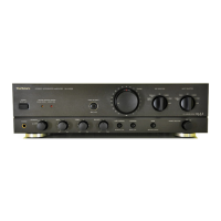
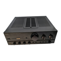
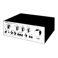
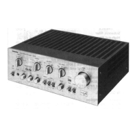
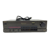
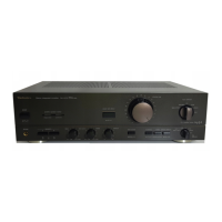
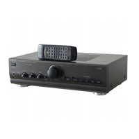
Describes power switch, indicators, input selectors, volume, and tone controls.

Special Function and Remote Controls

Covers loudness, subsonic filter, mode, and remote sensor functions.

Repair Preparation and Accessories

Before Repair Procedures

Power supply checks and protection circuitry explanation.

Included Accessories

Lists items provided with the unit.

Disassembly Procedures: PCBs

PCB Removal Steps

Steps for removing various circuit boards.

Power Voltage Setting

Instructions to set the correct power voltage for the unit.

Disassembly Procedures: External

Speaker and AC Connections

Connecting speakers and AC power cord.

Cabinet and Front Panel Removal

Steps to remove the outer cabinet and front panel assembly.

Disassembly Procedures: Internal

Internal Component Removal

Steps for removing power transistor, rear panel, AC inlet, phono PCB.

Main PCB and Power IC Removal

Procedures for removing the main PCB and power IC.

Maintenance and Adjustment Procedures

Foot Replacement and PCB Check

Procedure for replacing feet and checking main PCB.

Voltage Control Amplifier Adjustment

How to adjust the V-amp idling (ICQ).

Circuit Schematic Diagrams

Phono, Main, and Switch Circuit Diagrams

Schematics for phono EQ, main, and switch circuits.

Input Selector and Remote Sensor Circuit Diagrams

Diagrams for input selector and remote sensor circuitry.

Circuit Schematic Diagrams

Circuit Diagram Details

Continuation of circuit diagrams for various sections.

Circuit Schematic Diagrams

Circuit Diagram Details

Further continuation of circuit diagrams.

Circuit Schematic Diagrams

Circuit Diagram Details

Final continuation of circuit diagrams.

Printed Circuit Board Layouts

Main, Input Selector, Phono, Volume PCBs

Layouts for main, input selector, phono, and volume circuit boards.

Switch PCB Layout

Layout of the switch circuit board.

Printed Circuit Board Layouts

V-Amp and Remote Sensor PCBs

Layouts for V-amp and remote sensor circuit boards.

Component Identification and Wiring Guides

Operation, AC/Volt Adj, Power Switch PCBs

Layouts for operation, AC/Volt adj, and power switch PCBs.

Terminal Guides and Wiring Diagrams

Guides for ICs, transistors, diodes, and overall wiring.

Wiring Diagram and IC Terminal Functions

Wiring Connection Diagram

Overall wiring schematic of the unit.

IC801 Terminal Functions

Detailed pin functions for IC801 (Micro Computer).

Related product manuals