EasyManua.ls Logo

Technics SU-VX720 Service Manual

Technics SU-VX720
19 pages
To Next Page IconTo Next Page
Page #1 background imageLoading...
Page #1 background image
.
-
Suffix
for
‘e
.
pee
ere
|ModelNo.|
|
|
Great
Britain
Yea
oe
Hl
Le
a
nec
=
=
va
a
ECIFICAT
IONS
(DIN
45.500)
(|
Avia,
atte
Aydaricas:
a
Middle
Near
East
and.
a
Africa
doeeminate
|
qtiniverti
.
Oceania
rn
ee
oo
SIN
at
50
Ww
power
(4
ay
2x55
W
16
0)
PHONO
MM
cafe
PHONO
MC.
7
:
Va
SERA
9x70
We
O)
ee
—*
TUNER,
CD,
AUX,
TAPE,
TAPE
2IDAT
ee
vee
ie
2100
W
(4
Og
eS
Frequency
response
ee
*
M212.
5
Kitz
continudus
power
output
ee
UP
ae
_PHONO
ic
ft
AA
sane
de
|
9
x65
W
eee
|
both
ghannels
driven
(
OHO.
oe
os
4
7
f
a
.
TUNER,
cD,
AUK,
TAPE
1,
TAPE
2IDAT
otal
harmonic
distortion
=)
Pe
a
et
:
|
.
“03
a
ts
ted
power
at
20Hz~20kHz
0.007%
60)
a
ee
ene
we
ods
ape
srmodulation
distortion
(50.
Hz:
7
kHz=
=
4:1,
Dead
ee
|
op
sna
COSTES
Bot
ate
hy
See
ated
power
a
R607
%
@
Oye
TREBLE
©
:
dualhum
andnoise
YAMS.
Sd
sbeonie
fliter
.*
pingfactor
oe
60
(8
Q),
30
(4.9).
ee
ee
I
(vol
“3
adphones
output
levelrimpedance
es
540
mv/330
Q
aes
_,
Loudness
contro
(vo
ume
at
0
dB)
dd
whpedanne-
20
ys,
oe.
©
Output
voltage
i
or
B,
Bl:
WIRING,
is
|
7
7
4
Q~160
oF
TAPE
1,
TAPE
2/DAT
REC
OUT
and
B
oe
te
a
sa)
oe
8a~1
6
Q
Channel
balance
(AUX
250
Hz~6.
:
b
kiz):
:
ae
ee
.
Se
Channel
seporatien
fAUX.
:
hae
HONO.
MM
atte
nd
a
25
mVia7.
KO
ae
2
4
Siee
Se
1ONO.MC
|
7ONW220Q2-
6
6
=
GENERAL
oe
:
JNER,
CD,
AUX,
“TAPE
5
TAPEDAT
150
mV22KQ
oy
hono
maximum
input
woltaae
(
Ql
kHz,
AMS)
Oe
ee
Power
consumption
ee
Be
eee
.
160
mV
(IHF
66)
-»..
Power
supply
-
twitee’
Pes
le,
sak
My
|
oe
:
12
be
(HE
6000s
er
-
For{
EG).
fee).
(
(0),
(GN)
areas.
oy
a
4
ER
kg
|
-
AC
50
Hz/60
Hz.
HONO
MM
|
i
ae
“78
ae
(85
€B,
IHF
66)
eas
For
(Gc)
area’
AC
50
Hz/60
Hz.
110
vV—12?
w2
*HONO
MC
|
|
64
dB
(S=
250
wV,
66
dB,
!HF
oe
al
al
Dimensions
Weanee):
~
J
&BQx
JNER,,
cD,
AUX,
TAPE
1,
TAPE
2IDAT
aes
sicicial
i
|
get
Pe
:
7
91
3B
9
dB.
IHF:
‘66)
SE
ao
a
1
at
26
a8
power
(4
oy
-
ue
te
fe
ee
ee
ae
co
Noted:
ee
ee
ae
ee
Ne
2
es
Pigias
ne
©
i
Se
8
cB
:
ae
pas
Specticaions«
are
subject.
to
change
without
ne
:
,
Pees
ae
Weight
an
imensions
are.
approximate.
2
pues
co,
AUX,
TAP
E
1,
TAPE
=
UDAT
.
a
f
0-08
«oe
2.
Total
harmonic
distortion
is
measured
by
the
dig
|
|
‘i.
nn
enaiieste
vie
2
ape
Question and Answer IconNeed help?

Do you have a question about the Technics SU-VX720 and is the answer not in the manual?

Technics SU-VX720 Specifications

General IconGeneral
TypeStereo Integrated Amplifier
Input Sensitivity2.5mV (MM), 150mV (line)
Weight12.3kg
Frequency Response5Hz to 50kHz
Speaker load impedance4 ohms to 16 ohms
Signal to noise ratio86dB (MM)
Total Harmonic Distortion0.02%
Signal-to-Noise Ratio86dB (MM)
Dimensions430 x 150 x 360mm

Summary

Service Manual Overview

Technical Specifications

Detailed technical specifications according to DIN 45 500 standards.

Front Panel Controls and Indicators

Primary Controls

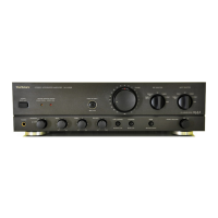
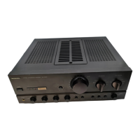
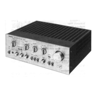
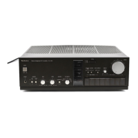
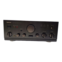
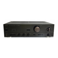
Details on core operational controls like power, volume, input, and speaker selectors.

Special Function Switches

Explanation of switches for tone, loudness, subsonic filter, mode, and source direct.

Component Connections

Connecting Audio Sources

Guides for connecting tuners, CD players, tape decks, and AUX devices.

Turntable and Remote Control Connections

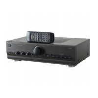
Instructions for connecting turntables, grounding, and remote control systems.

Setting the Power Voltage

Procedure for setting the correct power voltage for the region of use.

Speaker and Power Connections

Speaker Connection Types and Impedance

Guidance on connecting main, second, and bi-wired speakers with impedance requirements.

Disassembly and Servicing Safety

Servicing Safety Precautions

Important safety warnings for technicians performing disassembly and repairs.

Printed Circuit Board (PCB) Removal Procedures

Component Removal and Replacement

Schematic Diagrams - Core Circuits

Schematic Diagrams - Supporting Circuits

Schematic Diagrams - Functional Circuits

Amplifier, Volume, and Tone Circuit Schematics

Schematics detailing amplifier, volume control, and tone control stages.

Schematic Diagrams - Power and Control

Printed Circuit Board Layouts - Input and Main

Printed Circuit Board Layouts - Control and Sensor

Printed Circuit Board Layouts - Power and Control

Power Source, AC/Volt Adj., and Power Switch PCB Layouts

Layouts for Power Source, AC/Volt Adj., and Power Switch PCBs.

Wiring Connection Diagram

Measurements and Adjustments

Adjustment Procedures and Points

Guidance on performing voltage control adjustment and identifying adjustment points.

IC Terminal Functions and Block Diagram

Block Diagram - Signal Flow

Overall block diagram showing signal paths from inputs to outputs.

Block Diagram - Power and Control Systems

Block diagram illustrating power supply, control, and protection systems.

Replacement Parts List - Components

Cabinet, IC, Transistor, and Resistor Parts

List of replacement parts for cabinet, integrated circuits, transistors, and resistors.

Replacement Parts List - Detailed Values

Related product manuals