)
CONTENTS
i
INTRODUCTION
MAIN
P.G.
Diagram
....sssssssssssssseesssssssctsseseseene
1-8
SAFETY
PRECAUTION
oikecviclestecoecssasacsasonsssbishacluncies
L-2
FAS
P.C.
DiaQrarm.....tsesessssssessccseescssesssssseeeee
1-16
ARRANGEMENT
OF
CONTROL
PANEL
........essessesees
1-3
Measuring
Condition
of
FAJ
P.C.B.
w..csscessssesseseenee
11-18
KEYBOARD
RANGES
..vescesesesccstescssessesseseesesstesteseseeas
L5
FAN
PIG:
Board
icsigectisiatnt
icc
ataste
eek
11-18
INITIAL
SETTING
wu.sccscessssessessessesseseesecsesscsscsteseesrestsens
1-5
CPC
P.C
BOA
re
scc.casicsstiscritintiogetirencaeiek,
I-20
CONDUCTOR
SETTINGS
woscecscecscccescsssececeesesesseeeeees
1-6
CPL/CPR
P.C.
Board
......c.ccscseseee
1-22
TERIA
aie
oso
Jato
tss
cesses
eis
iced
1-7
CPL/CPR
P.C.
Diagram
...........-0-+-
11-23
PARTS
LOCATION:
visssisosscovibsandsdiconssncsnnscdonensdssespivaves
1-8
CPC
PC.
Diagrenniccstssessiccsccsactvaauisdeveins
1-24
DISASSEMBLY
INSTRUCTIONS
.....c.cecsceseeseeseseeeees
1-9
SYMPTOMS
WHICH
APPEAR
MKB1/MKB2/MKB3
P.C.
Board.....csscsssessesseeesees
1-28
TO
BE
SIGNS
OF
TROUBLE
.........csccscssscsessseeees
1-13
BEND
P.C.
Board
.........s:ssscsessssessssesseesseeees
1-29
ERROR
DISPLAY
......scssessessesssscssessesssssssessesscsssseseeees
1-15
MKB1/BEND
P.C.
Diagram............
11-30
ABOUT
THE
SELF-DIAGNOSTIC
FUNCTION.........
L-17
MKB2/MKB3
P.C.
Diagram
............
I-31
PRECAUTIONS
BEFORE
SERVICING
THE
MAIN
CIRCUIT
......ccsessesssessesscssecsssstesecsseeees
1-21
Ml
REPLACEMENT
PARTS
LIST
MIDI
IMPLEMENTATION
CHART
........essceseeseseseesees
1-23
P.C.
B.
AND
WIRING
PARTS
LIST
.....ccscsessesssessesesee
m-1
PRECAUTIONS
BEFORE
SERVICING
.......-.0..000000
1-25
CABINET
AND
CHASSIS
PARTS
LIST
.......cscssseseeee
Il-7
CABINET
PARTS
LOCATION.
...cssssssessssssssessssesesseessees
Il-9
i
SCHEMATIC
DIAGRAMS
PACKING
scsss
ict
sesh,
titted
iit
tes
etn
a
I-14
WIRING
CONNECTION
Diagram............scecesssscceseees
I-1
BLOCK
Diagram
........c.ccscscseccsscssssereccsnsssensesetneenseeaces
I-3
MAIN/LCDCN
P.C.
Board..........000+
1-6
Measuring
Condition
of
MAIN
P.C.B.
............sescceseees
I-7
SAFETY
PRECAUTION
@
Safety
Precaution
.
Before
servicing,
unplug
the
power
cord
to
prevent
an
electric
shock.
.
When
replacing
parts,
use
only
the
manufacturer's
recommended
components
for
safety.
.
Check
the
condition
of
the
power
cord.
Replace
if
wear
or
damage
is
evident.
.
After
servicing,
be
sure
to
restore
the
lead
dress,
insulation
barriers,
insulation
papers,
shields,
etc.
.
Before
returning
the
serviced
equipment
to
the
customer,
be
sure
to
make
the
following
insulation
resistance
test
to
prevent
the
customer
from
being
exposed
to
a
shock
hazard.
akon
@
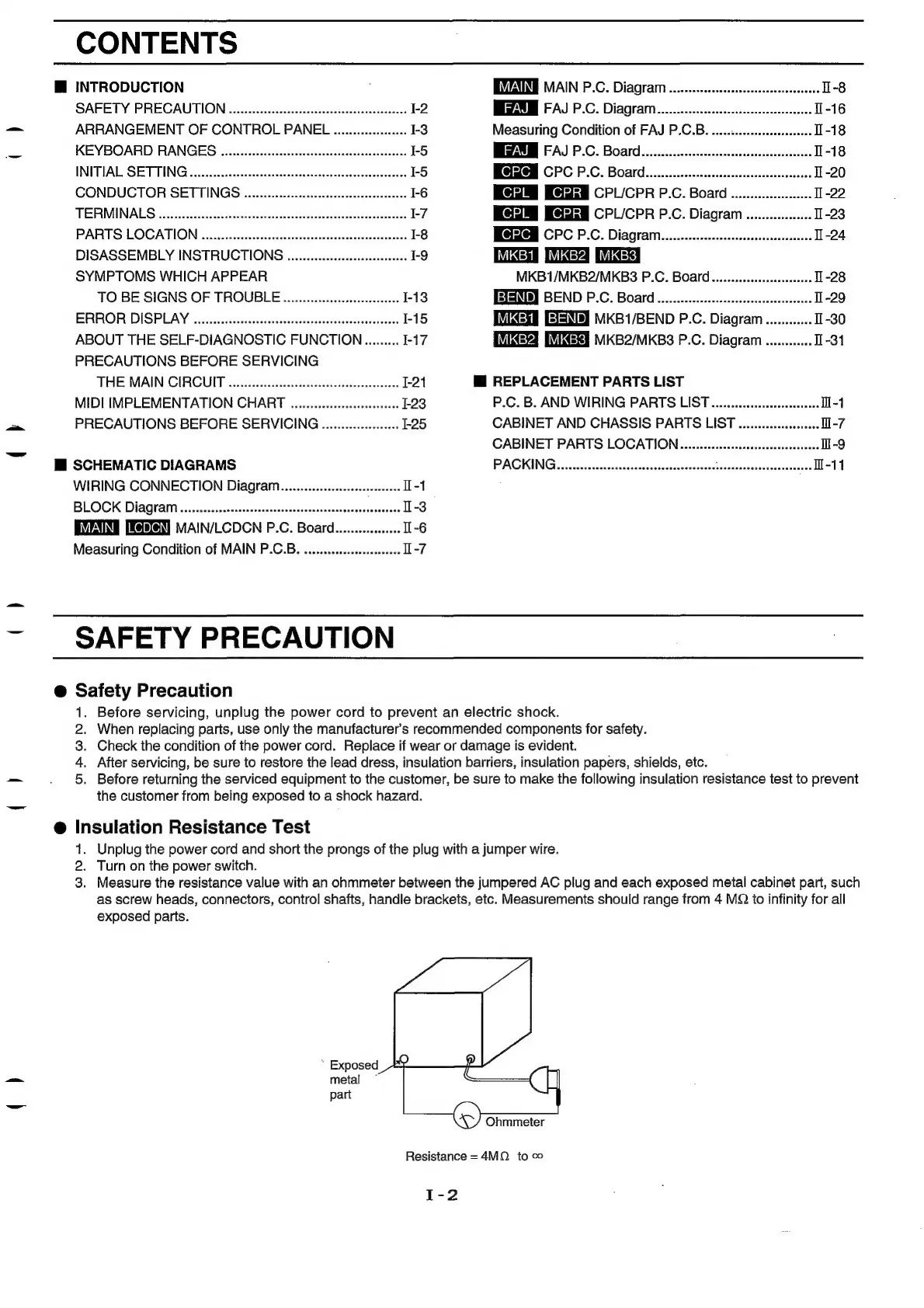
Insulation
Resistance
Test
1.
Unplug
the
power
cord
and
short
the
prongs
of
the
plug
with
a
jumper
wire.
2.
Turn
on
the
power
switch.
3.
Measure
the
resistance
value
with
an
ohmmeter
between
the
jumpered
AC
plug
and
each
exposed
metal
cabinet
part,
such
as
screw
heads,
connectors,
contro!
shafts,
handle
brackets,
etc.
Measurements
should
range
from
4
MQ
to
infinity
for
all
exposed
parts.
*
Exposed
metal
~
part
Ohmmeter
Resistance
=
4MQ.
to
co
I-2