106
"Step by step" setting of the heat quantity counter
You have the option of using 2 different volume flow encoders:
the pulse encoder VSG,
the FTS….DL, which is connected to the data link.
If you do not use a volume flow encoder, then you can only set a fixed volume flow.
In the following, the necessary settings are displayed "step by step".
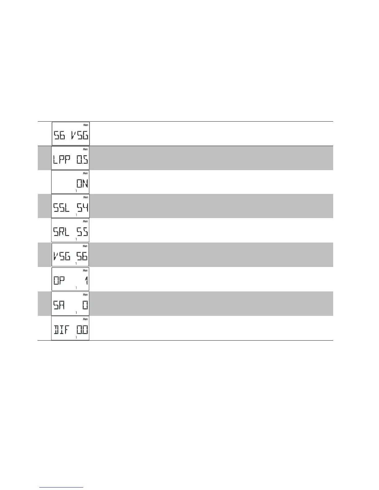
VSG (pulse encoder)
1
The VSG (pulse encoder) must only be connected to input 6, hence:
menu "SENSOR", sensor setting S6 to "S6 VSG"
2
Checking and possible alteration of the LPP value (litre per impulse)
3
Access to menu "HQC", selection of heat quantity counter 1 - 3, setting to
"ON"
4
Setting of the flow sensor in the SSL display, in the example shown,
sensor S4
5
Setting of the return sensor in the SRL display, in the example shown,
sensor S5
6
Entry of "S6" in the VSG display as the VSG is the sensor S6
7
Specification of the allocated outputs OP, dependent on the selected
program. With pump-valve systems, the allocated outputs must be
adjusted according to the basic diagram (e.g. with program 49: OP 12).
8
Indication of the antifreeze fraction SA in %
9
Possible sensor compensation as per the operating manual
 Loading...