SB series User’s manual
9
In the SBx-K series please note the following table regarding some limitations
on rays height due to the standards.
4 rays 3 rays 2 rays
1
st
ray height 300 mm 300 mm 400 mm
2
nd
ray height 600 mm 700 mm 900 mm
3
rd
ray height 800 mm 1100 mm
4
th
ray height 1200 mm
If the barriers are installed in a horizontal position, the optical bars must be
installed so that the distance that exists between the danger zone and the
furthest optical ray is equal to the result of the calculation using the previous
formula, but with the following parameters:
T= T1 + T2
where T1 = machinery’s response time in seconds.
T2 = barrier’s response time in seconds.
K = 1600 mm/s (approach speed of the body to the danger zone).
C = 1200 - 0.4 * H.
H = height of the optical rays compared to the floor.
S
= safety distance.
H
= the optical beam must have a height between
225 mm
and
1m
.
S
H
SB series User’s manual
10
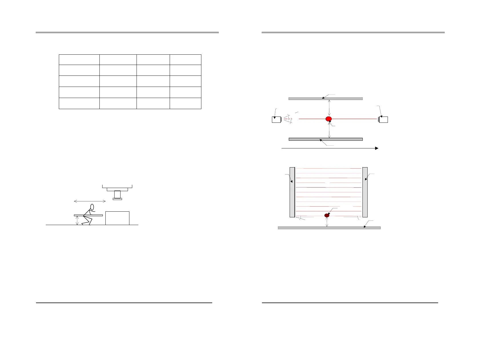
4.2 REFLECTING SURFACES
Should there be any reflecting surfaces, the distance must be sufficient to
safeguard against passive reflections.
The distance can be calculated with the formula:
A = 0.04366 * L
where ‘A’ and ‘L’ are expressed in mm
Object
TX barRX bar
2,5
q
2,5
Reflecting material
Reflecting material
L
2,5
q
A
Reflecting
surface
RX bar
TX bar
object
L
If several barriers are used, care must be taken that each transmitter does
not interfere with the receiver of a nearby barrier; install as follows: