SB series User’s manual
17
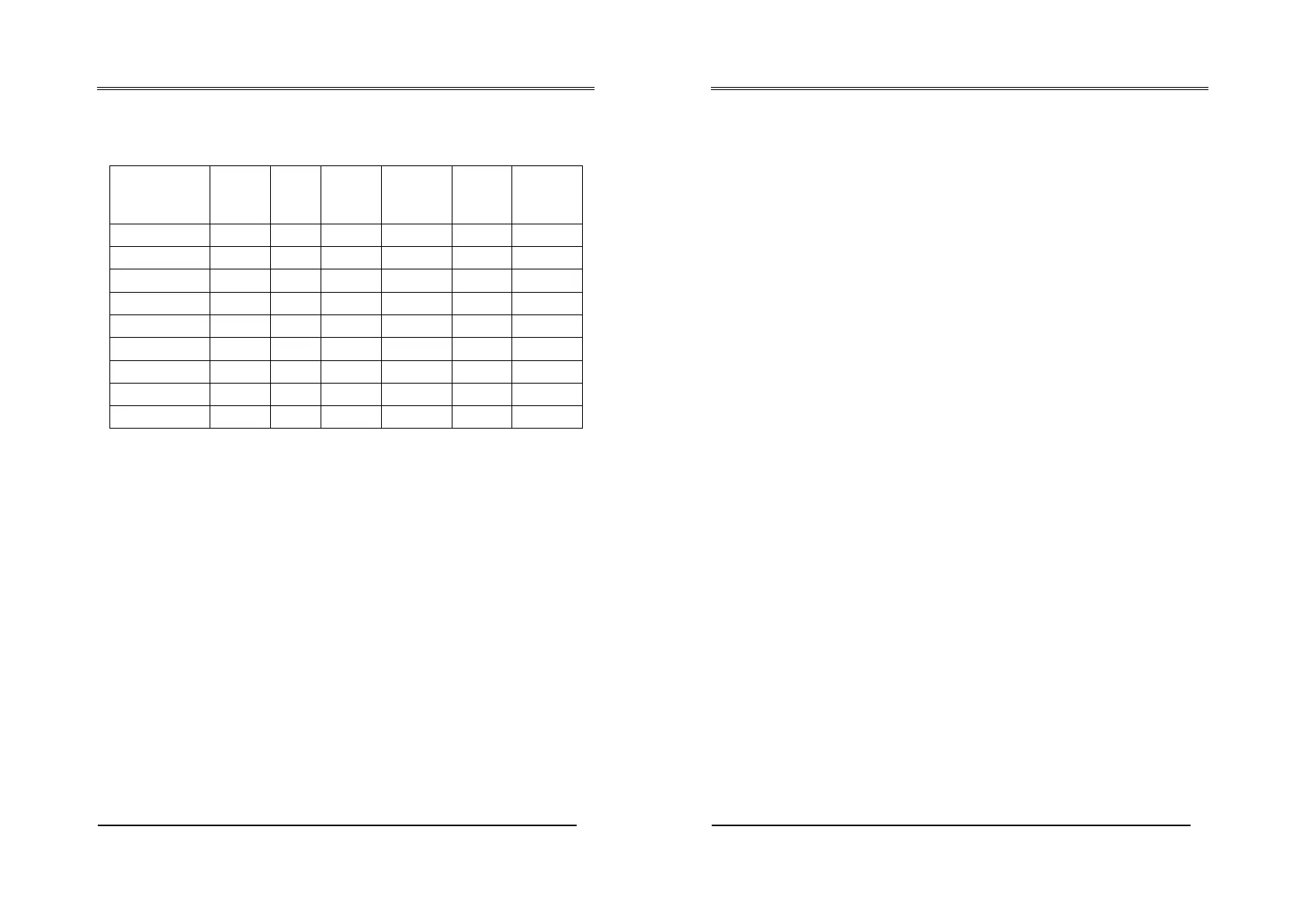
The following table shows the standard models available in the SBx-HR
series, based on the length of bars and their operating features.
All the models in the SBx-HR series guarantee 14 mm resolution.
Models
Height
controlled
mm
Total
height
mm
Total
number
of optical
units
Response
time ms
Number
of
modules
Number of
optical units
per module
SBx-HR-150 150 286 21 15 7 3
SBx-HR-300 300 389 42 18 7 6
SBx-HR-450 450 536 63 22 7 9
SBx-HR-600 600 683 84 24 6 14
SBx-HR-750 750 830 105 27 7 15
SBx-HR-900 900 977 126 30 6 21
SBx-HR-1200 1200 1271 168 36 8 21
SBx-HR-1500 1500 1565 210 42 10 21
SBx-HR-1650 1650 1712 231 45 11 21
SB series User’s manual
18
7 ALIGNMENT PROCEDURE
After completing correct mechanical assembly and connections, as
described in the previous sections, the barrier should be aligned as
follows:
x Disconnect the barrier’s power supply.
x Open the test/restart contact.
x Restore the barrier’s power supply.
x Adjust the direction of the barrier by moving the receiver or
transmitter. The 2 yellow leds located on the receiver will both be
lit when the barrier is aligned correctly.
x After aligning the barrier, secure the bolts firmly.
x Disconnect the power supply.
x Restore the barrier’s power supply (with the test contact closed);
it will enter operating mode.
x Complete all the checks described in the final controls and those
required for routine maintenance.