SB series User’s manual
23
x The single module muting function must be requested in the
purchase order.
x The single module muting function excludes the modular muting
function.
9.4 CRITERIA FOR INSTALLATION
All the muting sensors must be connected correctly in order to prevent their
incorrect placement from causing undesired requests for muting.
1. The muting sensors must recognise the whole length of the material (i.e.
pallets, vehicles...).
2. The sensors must be arranged so that the material is also recognised if it
has to be lifted for processing.
3. The effect of various transportation speeds in the field of muting on the
overall duration of muting must be taken into account, if any.
4. All the safety photocells and muting sensors must be arranged so that
the previous material clears the last muting sensor before the new
material reaches the first sensors.
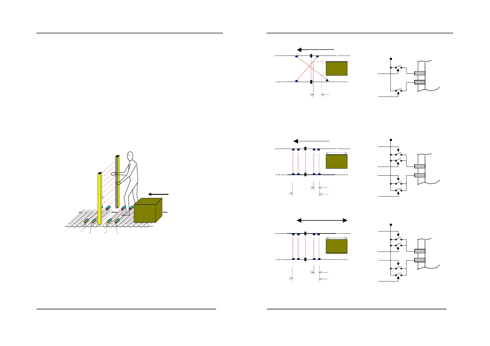
Example of installation of protection on a conveyor, which must allow a box to pass
through but not a person. The protection barrier
S
is connected to the control panel,
and A1, A2, B1 and B2 are temporarily excluded for the passage of the box via
sensors that enable muting. The contacts for these sensors are controlled on the
receiver unit.
Sensors
A
and
B
can be optical, mechanical, proximity sensors, etc., with closed
contact in the presence of the object to be detected.
The following pages show several examples of configurations with the use of
the muting function:
B1
A2
1
B2
S
SB series User’s manual
24
Application with two sensors:
S
B
d1 = D
Connection of the muting sensors:
Contact with A
Contact with B
24 V
DC
MUTE A IN
MUTE B IN
to the SB cable
Direction allowed
Application with four sensors and single direction for introduction of material:
1B1
S
2B2
d1
Connection of the muting sensors:
Contact with A1
Contact with A2
Contact with B1
Contact with B2
24 V
DC
to the SB
cable
MUTE A IN
MUTE B IN
D
L
v
Direction allowed
Application with four sensors and dual direction for introduction of material:
1B1
S
B2
2
d1
Connection of the muting sensors:
Contact with A1
Contact with A2
Contact with B1
Contact with B2
24 V
DC
to the SB
cable
MUTE A IN
MUTE B IN
D
L
Directions allowed



 To Next Page