USER MANUAL
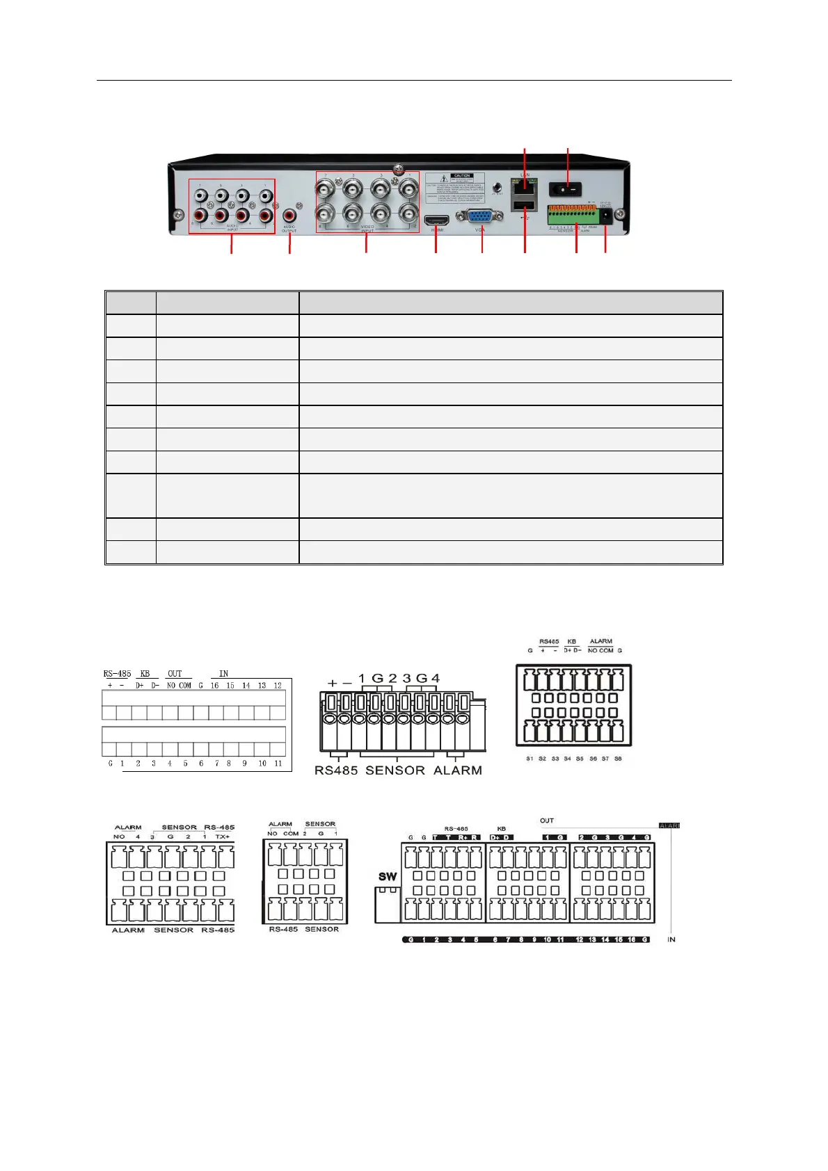
2.2 Rear Panel
SN
Physical Interface Connection
1
Audio output Audio signal output, RCA port
2
Video input Connect with CH1-4 (analog) video input device, standard BNC port
3
Audio input Connect with CH1-4 audio input signals, RCA port
4
HDMI Port Connect to HDMI monitor
5
VGA port Connect with VGA display devices, such as PC monitor
6
USB port Connect with U flash disk, disk burner, and other USB storage devices
7
LAN: Network port Connect with LAN, Ethernet and RJ45 port.
8
RS-485/Sensor/Alarm
RS485/Sensor/Alarm port. Connect by referring to the interface definition
below
9
Power port Connect with the power supply DC12V 3A, attached with the machine
10
Power switch Turn on /off power supply
The following diagrams shows the interface definition of sensor input / alarm output
/RS485:
Alarm input: Check your purchased alarm device and connect a G (GND) foot to the port marked
with “-” and connect the alarm channel to the port marked with “+”.
Alarm output: Two ports marked with OUT.
PTZ port: Check your purchased PTZ and connect to the two ports (+ -) marked with RS 485.
2 1 3 4 5 6 8 9
10
7
2