EasyManua.ls Logo

TECNA 3322 - User Manual

Default Icon
56 pages
Print Icon
To Next Page IconTo Next Page
Loading...
PUNTATRICI PENSILI DA PRODUZIONE
AIR OPERATED PRODUCTION SPOT WELDING GUNS
PINCES DE SOUDAGE POUR SERVICE INDUSTRIEL
PRODUKTIONS – PUNKTSCHWEISSZANGE
PINZA COLGANTE PARA ELEVADA PRODUCCION
FASCICOLO DOCUMENTAZIONE TECNICA
TECHNICAL DOCUMENTATION BOOKLET
DOSSIER DOCUMENTATION TECHNIQUE
TECHNISCHE DOKUMENTATION
FASCICULO DE DOCUMENTACION TECNICA
DISTRIBUTORE / DISTRIBUTOR / DISTRIBUTEUR / VERTRIEB / DISTRIBUIDOR:
EDIZIONE / EDITION / EDITION / AUSGABE / EDICION: 2008
TECNA S.p.A.
Via Grieco 25/27 - 40024 Castel S. Pietro Terme - Bologna ITALY
Pho. +39.051.6954400 - Tel. 051.6954410 - Fax +39.051.6954490
E-Mail:sales@tecna.net - vendite@tecna.net
ART. / ITEMS
3321 - 3322 - 3323 - 3324 - 3327- 3328
Question and Answer IconNeed help?

Do you have a question about the TECNA 3322 and is the answer not in the manual?

Summary

Technical Documentation Booklet

Air Operated Production Spot Welding Guns

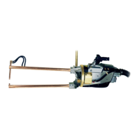
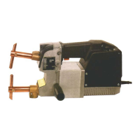
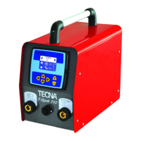
Manual for TECNA air-operated production spot welding guns.

Manufacturer and Conformity Declarations

Manufacturer Declaration

Declaration by the manufacturer regarding product conformity and standards.

Statement of Conformity

Product conformity statement referencing community directives and standards.

Technical Diagrams

Cooling Diagrams

Diagrams illustrating the cooling system for various spot welding gun models.

Pneumatic Diagrams

Diagrams illustrating the pneumatic system for the spot welding guns.

Dimensional Drawings

Detailed dimensions and measurements for different spot welding gun models.

Electrical Schematics

Handle Wiring Diagram

Wiring diagram for the handle assembly of TE300-TE450 models.

TE300;TE450 Electrical Schematic

Overall electrical schematic for TE300 and TE450 spot welding guns.

Control Unit and Power Module Connections

Schematic showing connections for control unit and power module.

Firing Module and Transformer Connections

Schematic showing connections for firing module and transformer.

Spare Parts Lists and Diagrams

Table 01: Suspension Group Components

Diagram and list of components for the suspension group.

Table 02: Lever-Transformer Group Components

Diagram and list of components for the lever-transformer group.

Table 03: Cylinder Group Components

Diagram and list of components for the cylinder group.

Table 04: Control Unit Group Components

Diagram and list of components for the control unit group.

Table 05: Optional Flow Switch Group Components

Diagram and list of components for the optional flow switch group.

Table 06: General Electrical Switch Group Components

Diagram and list of components for the general electrical switch group.

Table 07: Air Treatment Group Components

Diagram and list of components for the air treatment group.

TECNA 3322 Specifications

General IconGeneral
BrandTECNA
Model3322
CategoryWelding System
LanguageEnglish

Related product manuals