Do you have a question about the TECNA TE550 and is the answer not in the manual?
Lists key features like simplified programming, synchronous control, program storage, parameter settings, and language options.
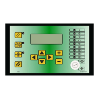
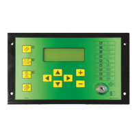
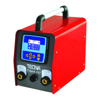
Explains the function of each button on the control panel for navigation, adjustment, and operation.
Describes the meaning of each LED indicator on the control panel for status and output signals.
Details the information shown on the main frame: program number, spot count, weld time, current, and conduction angle.
Explains the startup sequence, RESTART key, and essential safety precautions before operation.
Defines parameters for the welding cycle: program selection, working mode, and control mode.
Details the FIX mode for setting welding current by percentage, suited for difficult conditions.
Explains the IK mode for maintaining a stable welding current despite variations.
Describes the ENE mode for controlling welding by energy output, requiring careful parameter setup.
Explains key parameters like WORKING MODE, CONTROL MODE, and QUALITY-T, defining their functions.
Allows adjustment of parameters for simplified programming and better control unit configuration.
Configures parameters for stepper operations, used to compensate for electrode wear.
Explains how the stepper function compensates for electrode wear by gradually increasing current.
Contains parameters describing welder complexity, protected by a code for safety.
Used for copying parameter values between programs to expedite setup.
Displays input status for verifying external devices connected to the control unit.
Activates program sequence mode for automated welding spot selection.
Combines stepper function with electrode restoring to maintain welding quality.
Configures linear position sensors for measuring material thickness and indentation.
Crucial for reducing power line absorption and transformer dissipation during installation.
Identifies incorrect welds outside limits and describes WRONG signal activation.
Indicates the completion of the weld cycle via an output signal.
Indicates current activation during the weld cycle via an output signal.
Details connecting the TE550 to printers or PCs for data documentation.
Explains network connectivity for programming and data management.
Allows control unit to manage proportional valves and set welding pressure.
Enables measurement of welding pressure via an external sensor.
Details signals for optional boards, including error reset and sensor inputs.
Lists and explains system-level errors and their remedies.
Lists and explains welding operation errors and their remedies.
Lists and explains parameter configuration errors and their solutions.
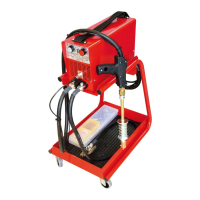
| Brand | TECNA |
|---|---|
| Model | TE550 |
| Category | Welding System |
| Language | English |