11
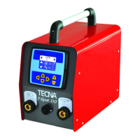
Art. / Item 7911-7913-7915
INTRODUCTION
CAREFULLY READ THIS MANUAL BEFORE
INSTALLING AND OPERATING THE WELDER.
The purpose of this instruction manual and of the enclosed
documents is to transfer the necessary information for using the
product in a proper and safe way. It includes pieces of information
relevant to safety, installation, use, maintenance and disposal of
the product.
This manual is addressed to the factory responsible in charge
who must release it to the personnel in charge of the welder
installation, use and maintenance. He/she must check that the
information given in this manual and in the enclosed documents
have been read and understood before operating the machine.
The manual must be stored in a well-known place, easy to reach,
and must be looked up each time even little doubts should arise.
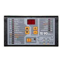
The welders marked with suffix P are equipped with the pulse
functioning mode, which can be excluded anyway. The pulse
stands for the power supply at regular intervals. It is possible to
carry 13 pulses out maximum (5 complete cycles) at an interval of
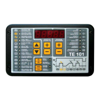
2 pause cycles. The pulses duration is adjustable through the
knob 66 (Picture 3).
These welders must be installed in industrial environments for
professional use only and are classified as class A resistance
welding equipment. This product is foreseen for being used neither
in domestic environment nor on low voltage public supply mains
supplying domestic buildings. This may cause radiofrequency
interferences.
All modifications, even slight ones, are forbidden because they
could compromise the machine’s safety and they should invalidate
the welder EC certification.
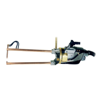
The welder has been designed for resistance welding of both
ferrous and non ferrous materials (stainless steel, brass). The
welder must not be used for other applications.
TECNA S.p.A is not responsible for any damage to both people,
animals, things and to the welder itself caused by either a wrong
use or the lack or the superficial observance of the safety warnings
stated on this manual, nor it is responsible for damages coming
from even slight tampering or from the use of not-suitable spare
parts, or of spare parts other than the original ones.
Only for EU countries:
In accordance with European Directive 2002/96/EC for
waste electrical and electronic equipment (RAEE), the
presence of this symbol indicates that the product shall
not be disposed of as urban waste. A separate collection
must be arranged for.
It is the user’s responsibility to dispose of this product correctly.
They should contact their local authority or retailer.
The unlawful disposal of these wastes is punished with sanctions.
The correct disposal helps to optimize the recovery, the recycling
and the reclaim of any materials and also reduces potential nega-
tive consequences for the environment and human health.
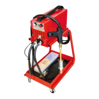
STANDARD ACCESSORIES
The welder is supplied equipped with:
N° 1 Allen keys set, 5-4-3-2 mm.
N° 1 additional handle (only for items 7911-7915)
N° 1 electrode sharpener Ø 12 (only items 7911)
N° 1 compressed air group complete with cutting device.
N° 1 air supply hose Ø 6, length 4 m supplied without plug.
N° 1 pair of arms item 7401 L=125 mm (only items 7911).
N° 1 instruction manual.
* Different voltages and frequency available on request
TECHNICAL FEATURES
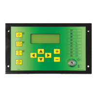
REFERENCE SYMBOLS
COLD The COLD parameter is used in the pulse operating
mode and indicates the time elapsing between one welding
pulse and the next one.
IMPULSE NUMBERThe IMPULSE NUMBER parameter
indicates the number of impulses used to carry out the
welding process. When this parameter is set to 0, the pulse
operation is disabled. The length of each impulse corresponds to
the time set in the WELD TIME or WELD TIME 2 parameter. When
working, the relevant led shows that this function is activated.
WELD TIME The WELD TIME parameter indicates the
current flow duration. It will be carried out with the power
value indicated in parameter CURRENT. When the pulse operation
is on, this parameter signals the duration of each pulse.
CURRENTThe value expressed in CURRENT indicates the
welding operating power.
7911 7913 7915
•••
2y65 2y65
2÷65
•••
Air Water Water
400 400 400
2,5 6 6
18 18 18
8,2 8,2 8,2
125 150 150
660 1520 1520
V 2,7 2,7 2,7
FFF
- 100 100
- - 2,5
bar 6,5 6,5 6,5
Nm
3
111
125 120 120
125 150 150
125 150 150
94 94 94
40 40 40
125 150 150
12,8 - -
-1613
14,8 19 15
< 70 < 70 < 70
< 2,5 < 2,5 < 2,5
cycles 4 6 6
kA 4,1 6,1 6,1
welds/min 11 15 15
Measurement conditions:
Weight with arms 150 mm
Weight with arms 500 mm
welding current
working rating
Standard arms throat depth L
Arms gap
Level of vibrations
Aerial noise
Max. water pressure
kg
m/s
2
kg
dB(A)
welding time
Max. electrodes stroke
with arms L=
Insulation class
mm
mm
mm
mm
mm
kg
Cooling water quantity
Secondary no load voltage
l/h
bar
daN
Weight with arms 125 mm
Max. force on electrodes
with arms L=
Cooling
Mains supply 50 Hz *
Nominal power at 50% kVA
Max. short circuit current
Time adjustment
Synchronous timer with SCR
cycles
Current adjustment 40÷100%
V
Max. welding power
with arms L=
kVA
kA
mm
A
Spot welder type
Thermal current at 100%
Air consumption for 1000
Pneumatic operation