2-18
(3) CN1 Interface Circuit and Wire Mode:
The diagram below introduces all interface circuit of CN1 and wire-method of host controller.
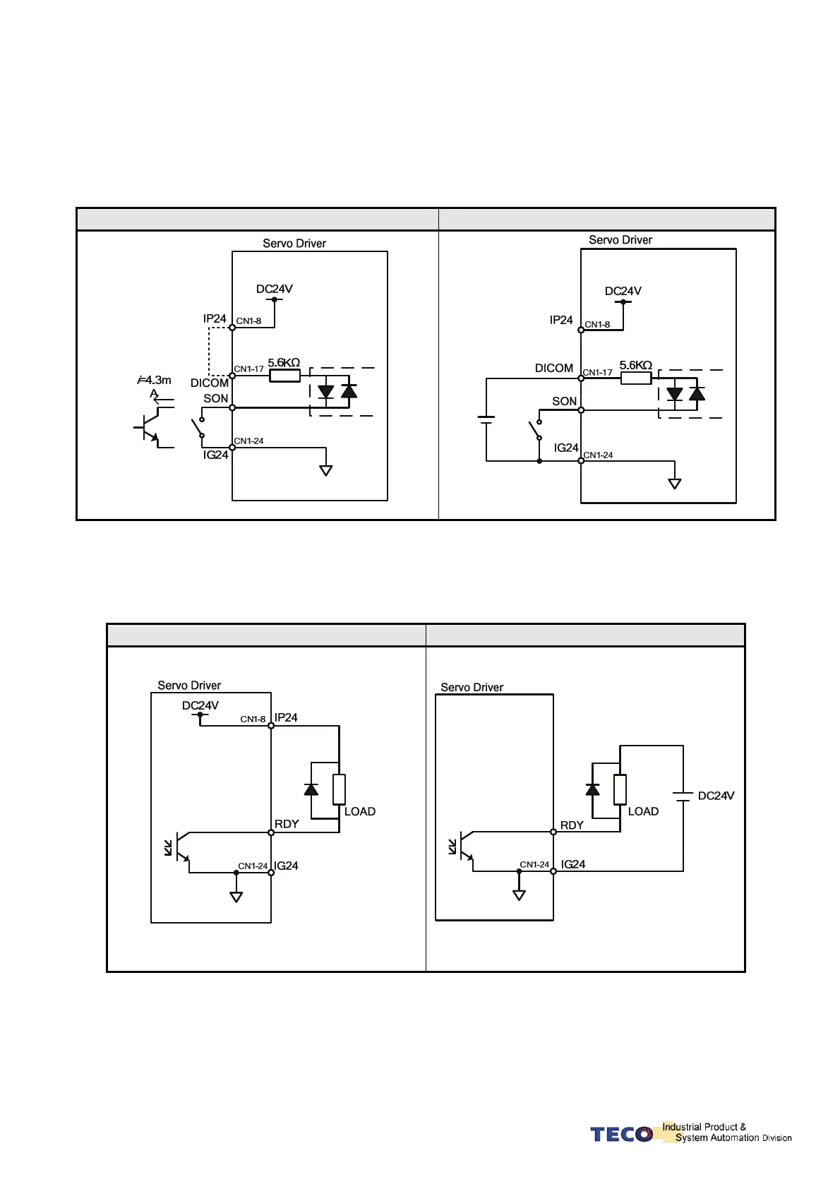
(a) Digital input interface circuit (IO1):
Digital input interface circuit can be operated by relay or collector transistor circuit. The relay should be the
low electric current, in order to avoid the faulty contacting. External voltage: 24V.
Internal 24V Power External 24V Power
(b) Digital Output Interface Circuit (IO2):
When using external power, please attention to the power polarity. Adverse polarity will case circuit
damage. Digital output is “Open Collector”. The maximum of external voltage is 24V; and the maximum
electric current is 10mA.
Internal 24V Power External 24V Power