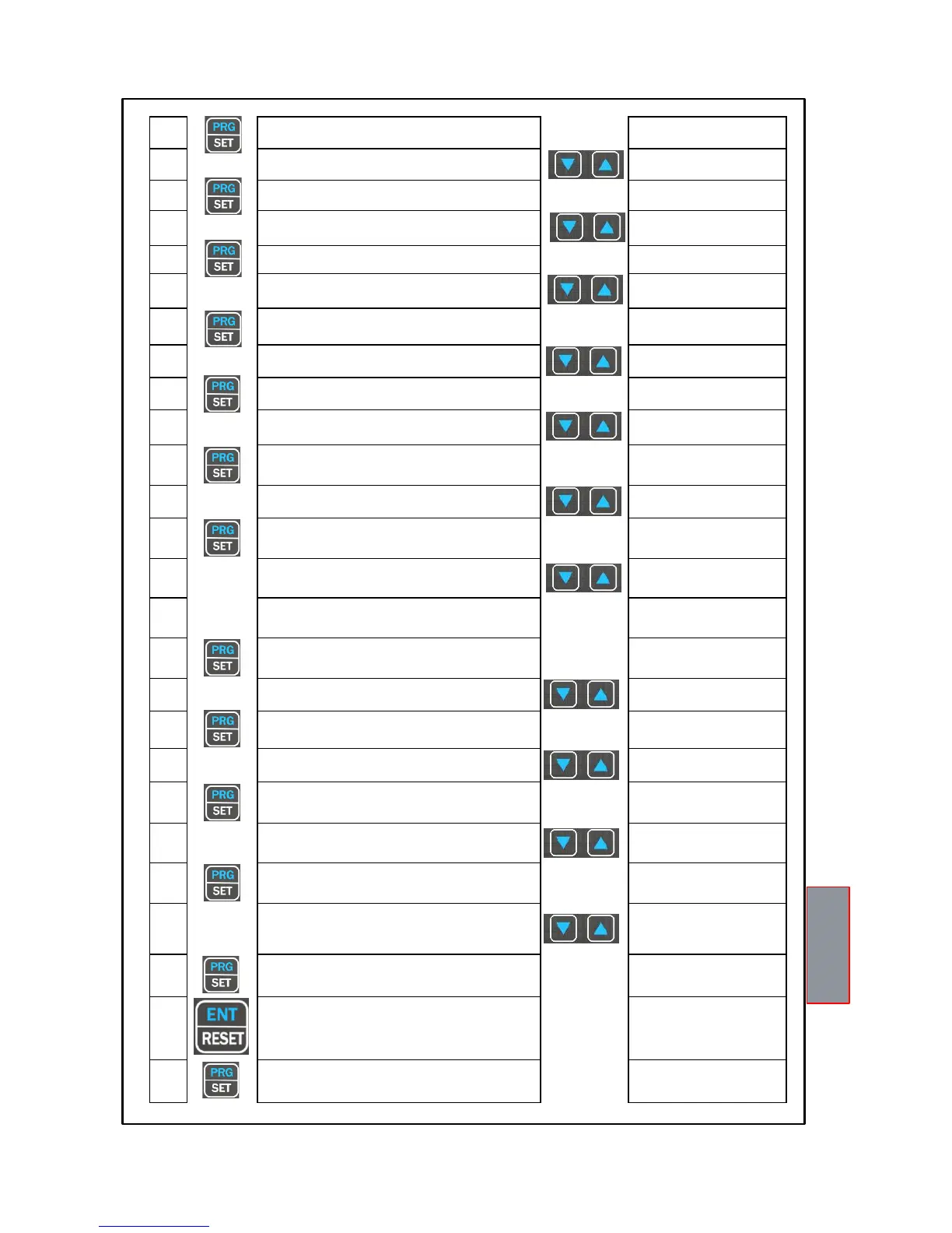
22
OFF (CH 4) is displayed, the FAN2 LED flashes
Default 35°C
23
Set the desired FAN2 OFF threshold
24
HFN (NO) is displayed
The FAN1-FAN2 LEDs flash
Fan cyclic test
for 5 min. every “n” hours
25
Set the desired number of hours
Default NO = function disabled
26
FCD (NO) is displayed
Fault for quick temperature
increase (°C/sec)
27
Set the desired value
(See FCD info on page 28)
Default NO
(function excluded)
28
VOT (NO) is displayed
(See VOTING on page 17)
29
Set YES or NO
Default NO
(function excluded)
30
The display shows FLS (ALARM) flashing LED ALARM
(info FAIL SAFE on page 27)
31
Set YES or NO
Default NO
32
The display shows FLS (TRIP) LED flashes TRIP
33
Set YES or NO
Default NO
34
The display shows FLS (FAULT) LED flashes FAULT
35
Set YES or NO
Default YES
36
For NT935 (BAS) version jumps to step 45
37
ADR <> "datum" is displayed
Modbus address
Default 001
38
Set the address
From 1 to 255
39
BDR <> "datum" is displayed
Modbus transmission speed
Default 19.2 Kb/s
40
Set the desired speed
From 2.4 Kb/s to 38.4 Kb/s
41
PAR <> "datum" is displayed
Parity bit selection Default EVE
42
Set the desired parity bit
None (N-1 or N-2), Even (EVE),
Odd (ODD)
43
420 <> "datum" is displayed
4.20 mA output programming
44
Select the 4.20 mA output desired
1-2-3-4; fixed channel
SCA: scanning
HOT: the hottest channel
Default HOT
45
END is displayed
End of programming
46
Press ENT to save the set data
and exit programming
Err: incorrect programming of
the LED values (note 6)
47
Return to step 1
See programming notes on page
16