EasyManuals Logo

TECSYSTEM NT935 User Manual

TECSYSTEM NT935
30 pages
To Next Page IconTo Next Page
To Previous Page IconTo Previous Page
Page #8 background imageLoading...
Page #8 background image
8
NT935
ASERIES
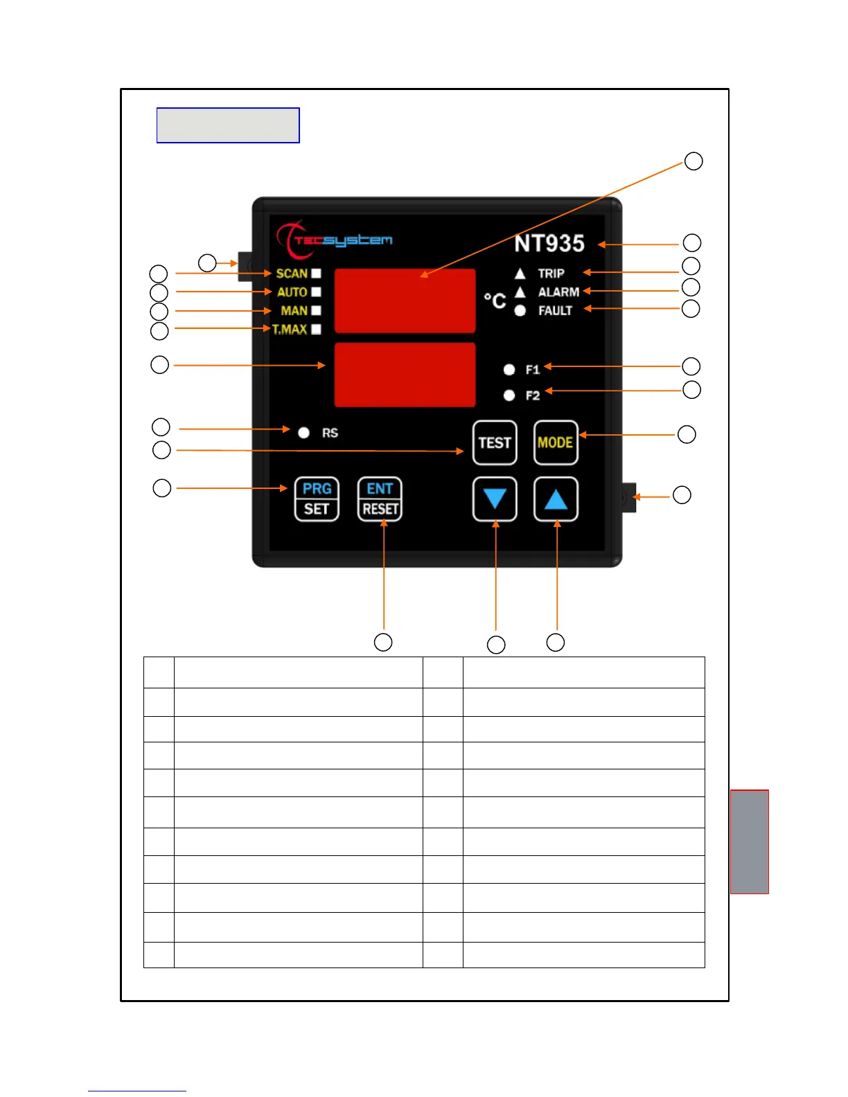
1) 3-digit temperature display 12) Enter/Reset button
2) Control unit series 13) Programming / Setting key
3) TRIP (red) LED 14) LED/relay test key
4) ALARM (yellow) LED 15) Modbus RS communication (green) LED (only AD)
5) FAULT (red) LED 16) 3-digit channel display
6) FAN 1 (yellow) LED 17) T-max mode selection (red) LED
7) FAN 2 (yellow) LED 18) Man mode selection (yellow) LED
8) Display mode selection key 19) Auto mode selection (green) LED
9) Fixing block 20) Scan mode selection (yellow) LED
10) UP key 21) Fixing block
11) DOWN key
FRONT PANEL
1
2
3
4
5
6
7
8
9
10
11
12
14
13
15
16
17
18
19
20
1MN0102 REV. 0
21

Questions and Answers:

Question and Answer IconNeed help?

Do you have a question about the TECSYSTEM NT935 and is the answer not in the manual?

TECSYSTEM NT935 Specifications

General IconGeneral
BrandTECSYSTEM
ModelNT935
CategoryController
LanguageEnglish

Related product manuals