INTRODUCTION TO THE MODBUS INSIDE MODULE
The MODBUS INSIDE expansion module is built in the monitoring unit and allows data transfer on a RS485 line with
MODBUS RTU protocol, maximum 32 devices.
OPERATING NOTES
For the module to work correctly, it is necessary to set the RS485 network set-up parameters: address, baud rate, parity
bit. See programming steps 37 to 42 on page 15.
The serial communication of the temperature control monitoring unit is active only when the NT935 AD is in temperature
control mode in one of the intended modes (Scan, Auto, Man and T.Max).
When other functions such as programming, programming display and relay test are activated, the ModBus
communication is temporarily deactivated.
DATA TRANSMISSION ON MODBUS NETWORK
The MODBUS INSIDE internal module allows connecting the NT935 control unit to an RS485 network with Modbus RTU
protocol in order to read the data shown in the MODBUS table on page 21 and write those in the notes for remote
programming; the module is always in slave mode.
The NT935 AD control unit is in communication with the network only when it is in temperature reading mode, while it is
inactive when in the following modes: display, programming and relay test.
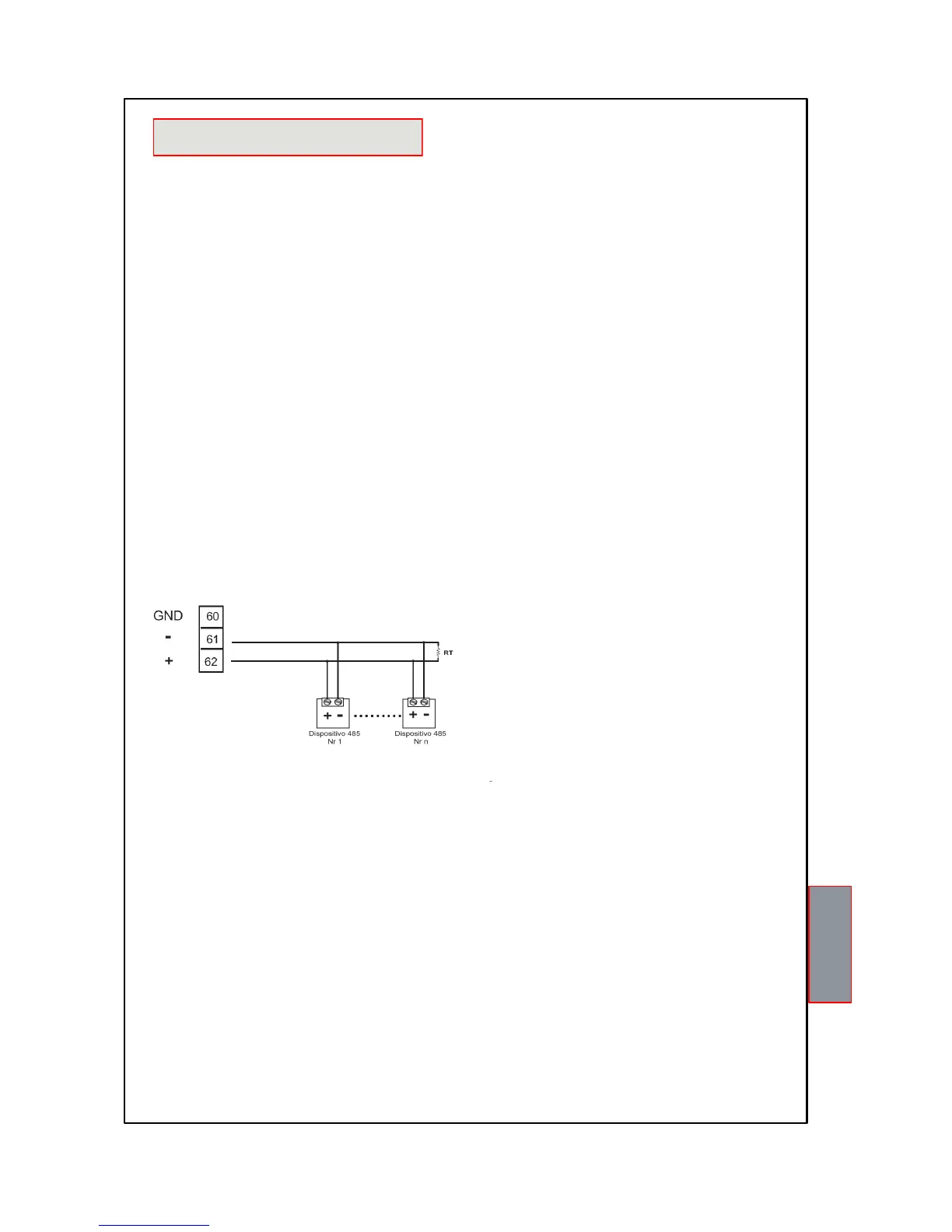
RS485 ELECTRICAL CONNECTIONS
As far as the signal cable to be used in order to ensure the correct network operation is concerned, we recommend you
follow the provisions of the EIA RS485 standard which suggests using a 24AWG twisted pair.
The twisted pair that connects units in RS485 might need a 120 ohm end resistor on the last unit of the series.
Connect the twisted pair paying attention to polarities and lay the network avoiding to make sharp bends or ring windings
in order not to modify line impedance. If necessary, the GND terminal for grounding is also available.
Always position the RS485 twisted pair far from power cables.
DATA FRAME
The frame in asynchronous transmission consists of: 1 start bit, 8 data bits, 1 parity bit (even or odd, if the parity has been
set) and 1 stop bit.
With selection parity (none) you can select N-1 (1 stop bit) or N-2 (2 stop bits).
Admitted baud rates are: 2400, 4800, 9600, 19200 and 38400.
If not otherwise specified, the word length (DATA) is 16 bits.