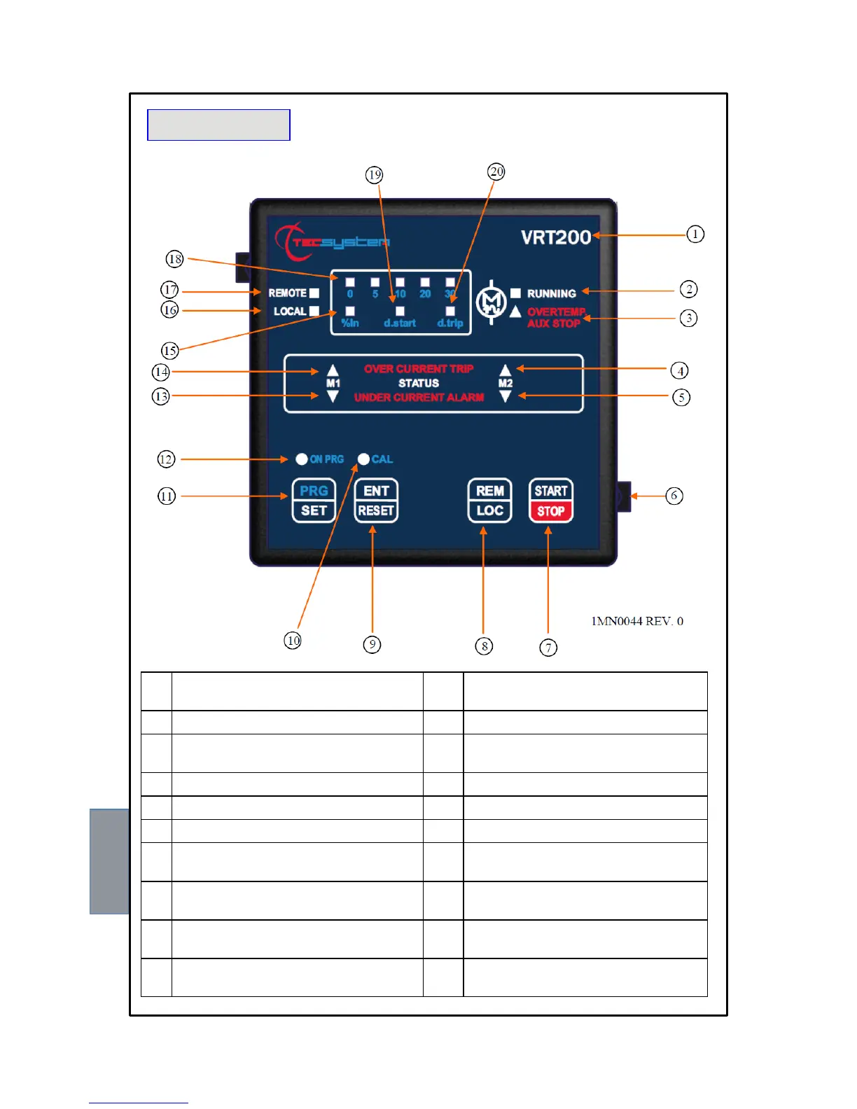
RT200
1) Control unit series 11) PRG/SET button: entering programming
and going on to the following step
2) Active (running) ventilation LED (green) 12) Programming phase ON PRG LED (yellow)
3) Overtemperature stop LED (red) (only
VRT200)
13) M1 motor in under-current LED (yellow)
4) M2 motor in over-current LED (red) 14) M1 motor in over-current LED (red)
5) M2 motor in under-current LED (yellow) 15) Current variation LED (yellow)
6) Fixing block 16) Fans' local management LED (red)
7) Fans' local START/STOP button 17) Fans' remote control LED (green)
8) Fans' control mode REM/LOC button
(REMOTE or LOCAL)
18) Programming selection LED (yellow)
(% In, d.start, d.trip)
9) ENT/RESET button: alarm reset and
programming data selection
19) Monitoring delay LED (yellow) at start up
d.start
10) Motors' auto-tuning phase LED (yellow) 20) Trip delay LED (yellow) d.trip
FRONT PANEL
7