RT200
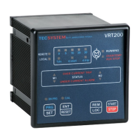
VRT200
1
2
5
3
1MN0046 REV. 0
4
1) AUX 1 - AUX 2 (COM) inputs fan
temperature control PTC sensor connection
4) Control unit and fan line supply 230V±10%
50-60 Hz 10 Amp.max
2) Remote enabling contact ENABLE 5) FAULT relay (fault signal)
3) M1-M2 motor line connection (5A max)
Note: with the power to the unit ON, the FAULT relay switches, contacts 8-9 open (NO) and 7-9 closed (NC).
FAULT 8-9 NC: ALARM FAULT OR POWER OFF FAULT 7-9: NC POWER ON
ELECTRICAL CONNECTIONS
789
789
9