16
CHAPTER 4 GOVERNORS AND LINKAGE
GENERAL INFORMATION
TC series engines are equipped with pneumatic (air vane) governors. The governor's function is to maintain a R.P.M.
setting when engine loads are added or taken away. Air vane governors are controlled by the air velocity created by fins
on the flywheel. Changes in the engine R.P.M. cause the air vane to move. This
movement opens the throttle shaft either by a link between the air vane and the throttle plate, or the air vane is mounted
directly onto the throttle shaft. The throttle is opened as the engine R.P.M.
drops and is closed as the engine load is removed.
This chapter includes governor assembly linkage and speed control illustrations to aid in assembly.
OPERATION
Engine R.P.M. changes cause an increase or decrease in
velocity exerts pressure on the air vane while a governor
spring exerts pressure against the air velocity force. The
air vane pivots on the engine blower housing base or is
attached to the throttle shaft of the carburetor. As an
engine load is applied and the engine's R.P.M drop, the air
velocity also drops, allowing the governor spring to pull
open the
throttle shaft and increase engine speed (diag. 4-1).
If the engine uses a remote speed control, the bowden
shaft. Moving the speed control plunger results in
changing the governor spring tension which increases or
decreases the engine's governed speed.
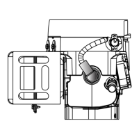
COMPONENTS
TYPE I
1. AIR VANE
2. BACKLASH SPRING
3. GOVERNOR LINK
4. GOVERNOR SPRING
5. MOUNTING SCREW
6. SPEED ADJUSTMENT SCREW
7. SPEED CONTROL BODY
8. SPEED CONTROL LEVER
9. SPEED CONTROL PLUNGER
3.
9.
6.
7.
1.
4.
4.
2.
8.
1.
5.
TYPE II
TYPE II
TYPE I
4-1
4-2
Insert Throttle Link
Spring Hooked
In Notch
 Loading...