4
www.teejet.com
BoomPilot
®
PRINCIPLE OF OPERATION
The BoomPilot system controls the sections valves according to the GPS position. The GPS makes it possible to avoid overlaps or skips.
The Section Driver Module (SDM) is designed for switching active high when spraying. This means that a 12V signal is issued to control the
corresponding section valve.
The SDM is connected in parallel with the controller section switches.
The BoomPilot controls the section valves in automatic mode, and the controller section switches should be set to off unless the operator
wants to override the auto mode and thus force spraying.
The BoomPilot monitors the controller section switches that controls the valves in manual mode. The the Master switch can be used both in
automatic mode as well as in manual mode.
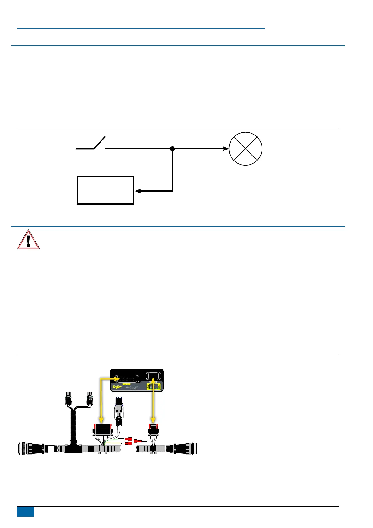
Figure 2: Principle of operation
SDM
Controller Section Switch
Valve
INSTALLATION
If there are questions concerning the installation of the BoomPilot system on this vehicle, or due to the changes in component
specications the parts supplied in the kit are not exactly as presented in this document, please contact your dealer or TeeJet
Customer service representative for clarication before installation. TeeJet Technologies is not responsible for misuse or incorrect
installation of the system.
NOTE: All references to left and right are stated as if the user is seated in the driver’s seat.
NOTE: BE VERY CAREFUL TO ABSOLUTELY SECURE ALL CABLES AND HOSES SO THAT THEY DON’T INTERFERE WITH THE MANY
MOVING PARTS OF THE MACHINE!
1. LOCATE THE CONNECTION POINT FOR THE SDM HARNESS
Locate the existing system’s ow control harness as it routes up to the side of the John Deere console.
2. MOUNT & CONNECT SDM
1. Mount SDM (E) as shown where LED’s can be seen for troubleshooting.
2. Connect SDM (E) to BoomPilot Harness (C).
Figure 3: Connect SDM
xxx-xxx
xxyyxx
RLC-System
VRS
B A
B A
A B
Section Power
E
C