6
www.teejet.com
BoomPilot
®
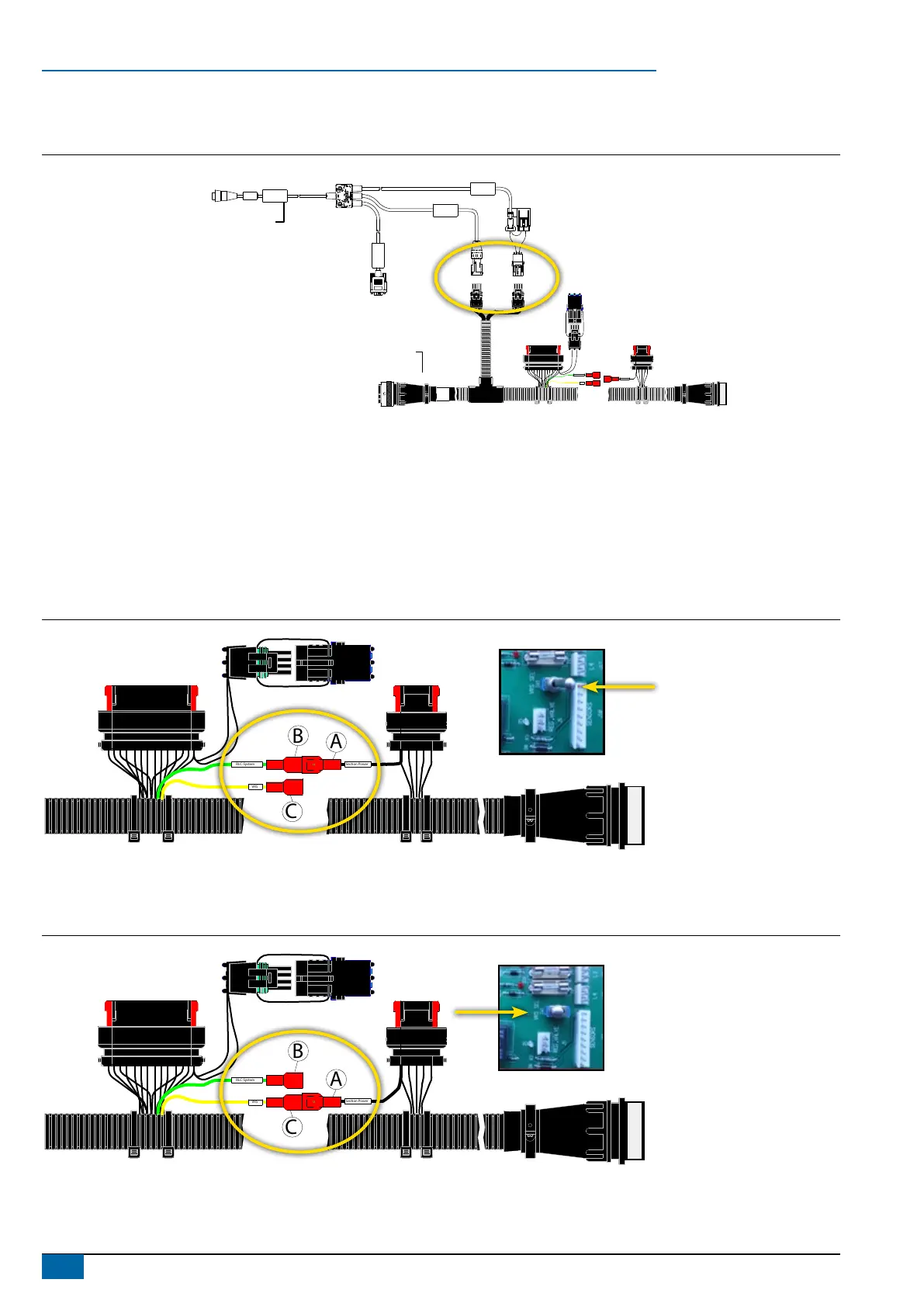
4. CONNECT POWER/CAN/DATA CABLE TO BOOMPILOT HARNESS
Connect Power/CAN/data cable (B) to BoomPilot harness (C).
Figure 7: Connect power/CAN/data cable to BoomPilot harness
POWER IN
CAN
RS-232
Power/DATA
45-05626
Power/CAN/Data Cable
BoomPilot Harness
xxx-xxx
xxyyxx
RLC-System
VRS
B A
B A
A B
Section Power
B
C
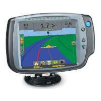
5. SETTING CIRCULATION SYSTEM TYPE ON BOOMPILOT HARNESS
The BoomPilot Harness (C) covers two different John Deere Sprayer types:
• Sprayers with Ring Line Circulation System (RLC-System).
• Sprayers with Vacuum Re-circulation System (VRS).
Ring Line Circulation System
Connect A to B (Section Power to RLC-System) ‘VRS Switch’ in postion ‘Non VRS’.
Figure 8: Ring Line Circulation System
RLC-System
VRS
B
C
A
B A
Section Power
Switch in Junction box
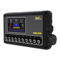
Vacuum Re-circulation System
Connect A to C (Section Power to VRS). VRS switch in position ‘VRS’
Figure 9: Vacuum Re-circulation System
B A
RLC-System
VRS
B
C
A
Section Power
Switch in Junction box