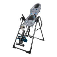
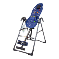
CORRECT
Handles are assembled correctly.
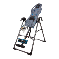
INCORRECT
Handles are switched / need to be corrected.
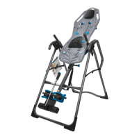
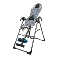
Handle Installation
Figure 22: Loosen the Handle Adjustment
Knobs on the right and left Handle Support
Tubes by turning the knobs counter-clockwise,
then pulling outward.
Locate the Handles, noting Right and Left
markings. With the top of the handles
pointing outward, insert both Handles into
the corresponding Handle Support Tube.
Adjust Handles as desired and tighten Handle
Adjustment Knobs by releasing into a hole
setting and then rotating clockwise.
STEP 6
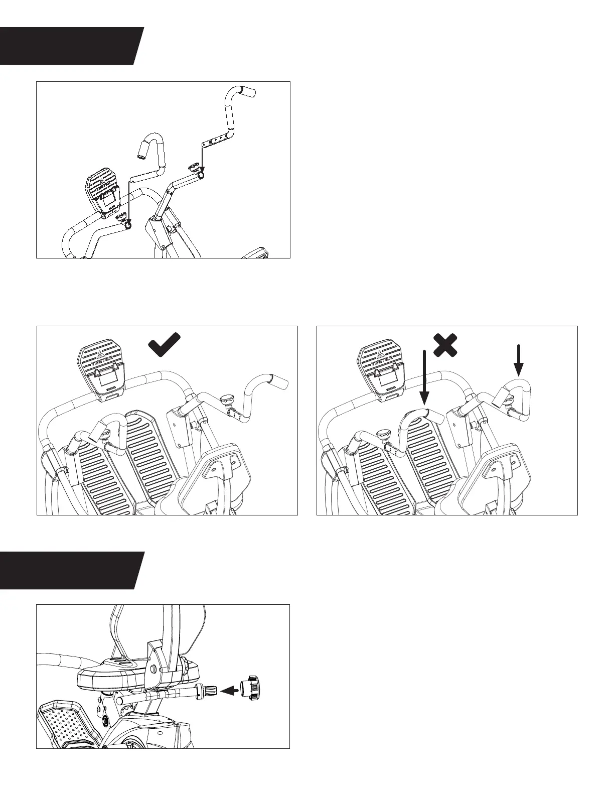
STEP 7
ASSEMBLE HANDLES
ASSEMBLE RESISTANCE GRIP
12
Figure 22
Figure 25
Figure 23 Figure 24
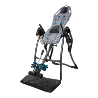
Resistance Grip Installation
Figure 25: Locate the Resistance Grip. Align the
recessed notch on the Resistance Grip with the
number 13 on the Resistance Base Assembly.
Slide the open end of the grip over the
Resistance Base Assembly so that the grooves
on the grip and base align. Push to snap into
place.