11
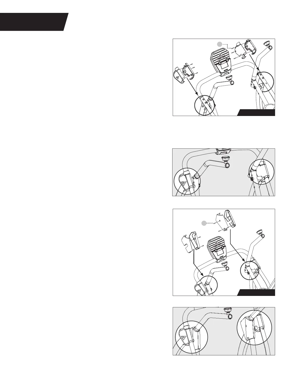
Pedal Arm Joint Cover Sets Installation
Figure 20: Locate the Pedal Arm Joint Cover
Sets, noting Right and Left markings.
Pair each set over the corresponding Right and
Left Pedal Arm Joints.
60
Phillips Head
Screw
60
Phillips Head
Screw
Upper Front Leg Cover Sets Installation
IMPORTANT: Make sure the Speed Sensor Wire sits
under the Left Upper Front Leg Cover Set and is
not pinched during installation.
TIP: In order to gain better access to the screw
holes while assembling the Upper Front Leg Cover
Sets, adjust the position of the Pedal Arm Joints
by pushing forward or pulling backward on the
Handle Support Tubes.
STEP 5
ASSEMBLE COVER SETS
Figure 20-21: Use the Step 5 Hardware Kit to install
the Pedal Arm Joint Cover Sets. Partially tighten 2 ×
Phillips Head Screws on each set as shown. Ensure they
are properly aligned and proceed to fully tighten the
Phillips Head Screws with the Screwdriver.
Figure 18-19: Use the Step 5 Hardware Kit to install
the Upper Front Leg Cover Sets. Partially tighten 3 ×
Phillips Head Screws using the Screwdriver provided
on each set as shown. Ensure they are properly
aligned and proceed to fully tighten the Phillips
Head Screws with the Screwdriver.
Figure 18: Locate the Upper Front Leg Cover Sets,
noting Right and Left markings. Pair each set over
the corresponding Right and Left Upper Front Leg.
Figure 21
Step 5 Hardware
Figure 20
Figure 19
Step 5 Hardware
Figure 18