10
108
Bolt
109
Curved Washer
LEFT/RIGHT
REVISIONS
ENGR
DATE
REV
SHT
ZONE
DESCRIPTION
NMS
10/18/2017
A
1
8D A1: RELEASE FOR PATENT
PARTS LIST
ITEM
QTY
NET DIMENSIONS/DESCRIPTION
NOTE
MATERIAL
SHT
REVISION STATUS
SHT
1
REV
A
8
A
1234567
D
C
B
C
A
D
B
5 3 16 248 7
8
A
1234567
D
C
B
C
A
D
B
5 3 16 248 7
handle assy
SHEET 1 OF 1
REV
PROJECT:
DRAWN
UNLESS OTHERWISE NOTED
SURFACE ROUGHNESS PER ANSI B46.1
DIMENSIONING PER ASME Y14.5-2009
WELD SYMBOLS PER AWS A2.4
FINISH:
UOS 63RMS ON
MACHINED
SURFACES OR
AS PROCURED
.X
.XX
.XXX
ANGLE
EXPECTATIONS PROPRIETARY
THE INFORMATION CONTAINED HEREIN
IS PROPRIETARY TO EXPECTATIONS AND
SHALL NOT BE REPRODUCED IN WHOLE
OR IN PART OR USED FOR ANY PURPOSE
EXCEPT WHEN SUCH USER POSSESSES
DIRECT WRITTEN AUTHORIZATION
FROM EXPECTATIONS LLC
SCALE: FULL
SIZE:
D
A
TOLERANCES
UNLESS NOTED
=
.1
=
.03
=
.005
=
1
NICK SOLLER
FILLET RADII: .005-.010
CORNER BREAK: .005-.010
ALL DIMENSIONS IN INCHES
EXPECTATIONS LLC
PUYALLUP, WA 98391
DRAWING
PROJECT NAME HERE
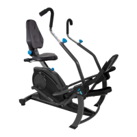
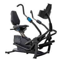
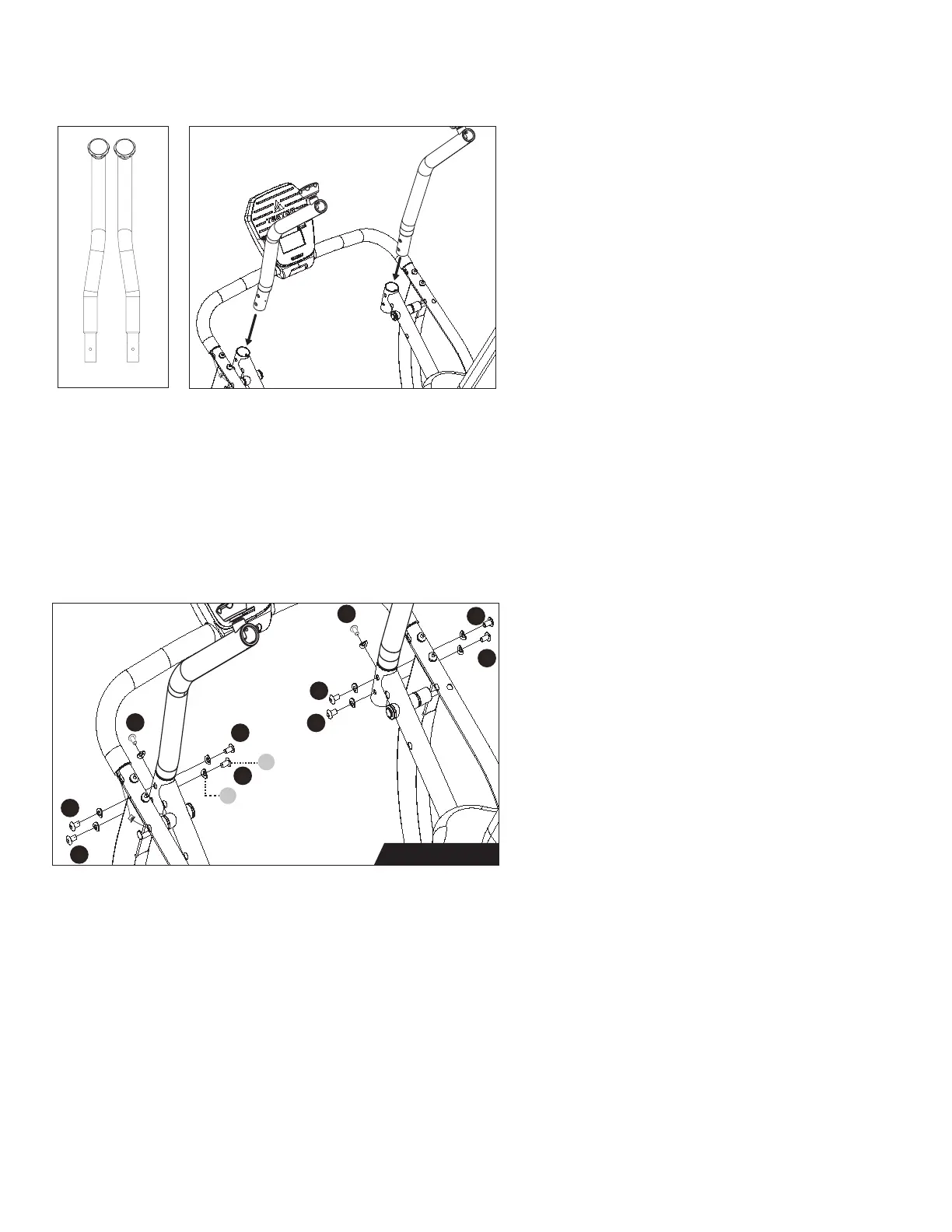
LEFT / RIGHT
Handle Support Tube Installation
Figure 16a-16b: Locate the Handle Support
Tubes, noting Right and Left markings.
Insert the bottom of each Handle Support
Tube into the top of the Upper Pedal Arm.
Figure 17: Use the Step 4b Hardware Kit
to attach the Handle Support Tubes.
IMPORTANT: Very loosely install 10 x Bolts
with 10 x Curved Washers 2-3 turns. The
Curved Washers should wrap around
the shape of the Upper Pedal Arms.
After all hardware has been installed 2-3
turns, there should still be 1-2 washer
thicknesses of space between the washer
and the base metal. This is important for
the next step so that the Handle Support
Tubes properly move into place as the
hardware is fully tightened. Proceed to
tighten all 10 Bolts in the EXACT order as
shown with the numbers in Figure 17 with
the Allen Wrench.
Figure 16bFigure 16a
Step 4b Hardware
Figure 17
1
2
5
3
4
9
8
10
6
7