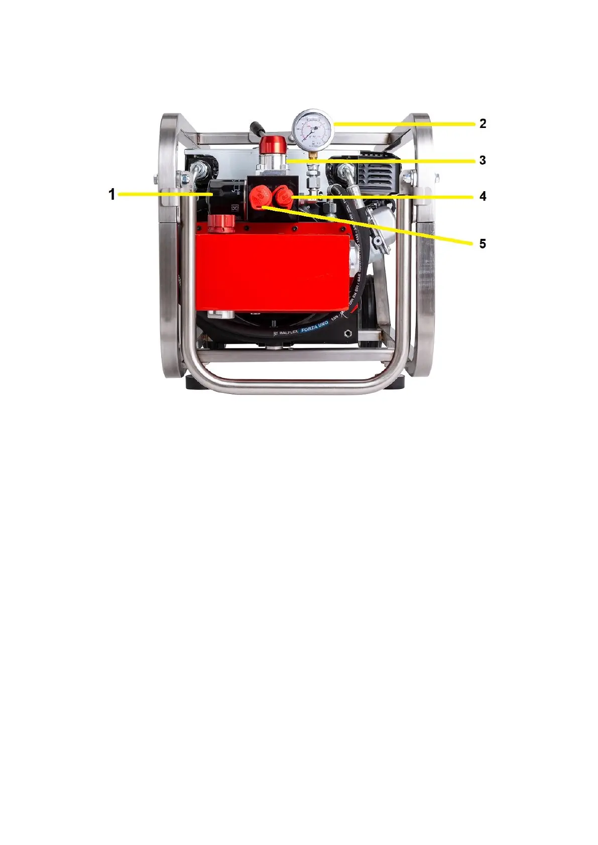
VIEW OF THE CONTROL VALVE BLOCK
Fig. 2 THE VALVE PLATE is the group that includes all hydraulic control components, the part is
obtained working two laminated aluminium blocks.
1 - OIL FILTER for hydraulic circuit
2 - PRESSURE GAUGE is positioned in the center for reading the pressure.
3 - ON/OFF FLOW LEVER is the lever that controls the distribution valve that delivers oil to tools , the
central position in the illustration is the OFF position where the tools are still , the lever must be put in
this position before start and put off motor.
TWO POSITIONS HYDRAULIC CONTROL VALVE
The lever has two positions:
- LEFT POSITION – Pressure out from the circuit
- CENTRAL POSITION OFF – Pressure in hold/stop/neutral it is the engine starting position (see
position in the picture)
4 - QUICK COUPLING – PRESSURE LINE
5 - QUICK COUPLING – RETURN LINE