Operating Instructions—2213 Service
CONTROLS, CONNECTORS, AND INDICATORS
The following descriptions are intended to familiarize
the operator with the location, operation, and function of
the instrument's controls, connectors, and indicators.
POWER, DISPLAY, AND
PROBE ADJUST
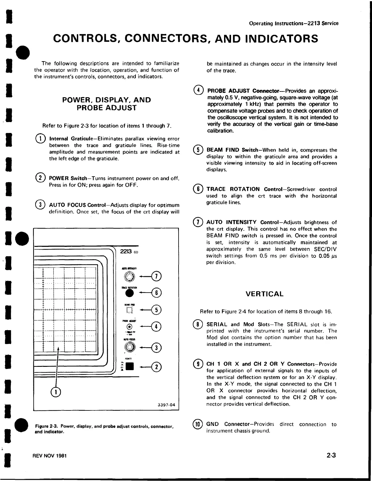
Refer to Figure 2-3 for location of items 1 through 7.
^ f ) Internal Graticule—Eliminates parallax viewing error
between the trace and graticule lines. Rise-time
amplitude and measurement points are indicated at
the left edge of the graticule.
© POWER Switch—Turns instrument power on and off.
Press in for ON; press again for OFF.
( ? ) AUTO FOCUS Control—Adjusts display for optimum
definition. Once set, the focus of the crt display will
be maintained as changes occur in the intensity level
of the trace.
© PROBE ADJUST Connector— Provides an approxi
mately 0.5 V, negative-going, square-wave voltage (at
approximately 1 kHz) that permits the operator to
compensate voltage probes and to check operation of
the oscilloscope vertical system. It is not intended to
verify the accuracy of the vertical gain or time-base
calibration.
( ? ) BEAM FIND Switch—When held in, compresses the
display to within the graticule area and provides a
visible viewing intensity to aid in locating off-screen
displays.
( ? ) TRACE ROTATION Control—Screwdriver control
used to align the crt trace with the horizontal
graticule lines.
( ? ) AUTO INTENSITY Control—Adjusts brightness of
the crt display. This control has no effect when the
BEAM FIND switch is pressed in. Once the control
is set, intensity is automatically maintained at
approximately the same level between SEC/DIV
switch settings from 0.5 ms per division to 0.05 /us
per division.
VERTICAL
Refer to Figure 2-4 for location of items 8 through 16.
( ? ) SERIAL and Mod Slots—The SERIAL slot is im
printed with the instrument's serial number. The
Mod slot contains the option number that has been
installed in the instrument.
( ? ) CH 1 OR X and CH 2 OR Y Connectors—Provide
for application of external signals to the inputs of
the vertical deflection system or for an X-Y display.
In the X-Y mode, the signal connected to the CH 1
OR X connector provides horizontal deflection,
and the signal connected to the CH 2 OR Y con
nector provides vertical deflection.
Figure 2-3. Power, display, and probe adjust controls, connector,
and indicator.
GND Connector—Provides direct connection to
instrument chassis ground.
REV NOV 1981 2-3
 Loading...


