Operating Instructions—2213 Service
10X PROBE—Indicates the deflection factor
selected when using a 10X probe.
MHz OSCILLOSCOPE
3397-05
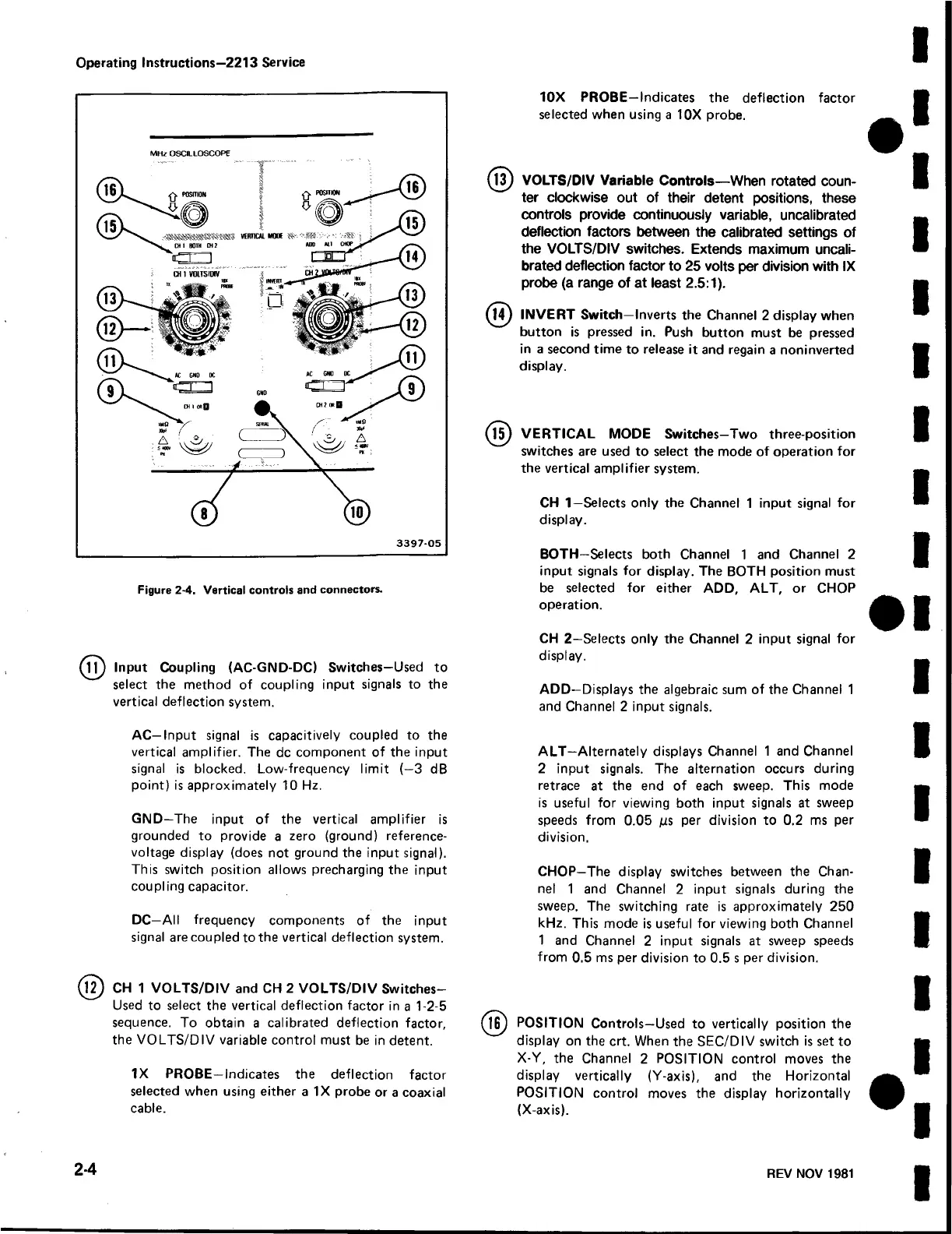
Figure 2-4. Vertical controls and connectors.
Input Coupling (AC-GND-DC) Switches—Used to
select the method of coupling input signals to the
vertical deflection system.
AC—Input signal is capacitively coupled to the
vertical amplifier. The dc component of the input
signal is blocked. Low-frequency limit (—3 dB
point) is approximately 10 Hz.
GND—The input of the vertical amplifier is
grounded to provide a zero (ground) reference-
voltage display (does not ground the input signal).
This switch position allows precharging the input
coupling capacitor.
DC—All frequency components of the input
signal are coupled to the vertical deflection system.
]2 ) CH 1 VOLTS/DIV and CH 2 VOLTS/DIV Switches-
Used to select the vertical deflection factor in a 1-2-5
sequence. To obtain a calibrated deflection factor,
the VOLTS/DIV variable control must be in detent.
IX PROBE—Indicates the deflection factor
selected when using either a IX probe or a coaxial
cable.
VOLTS/DIV Variable Controls—When rotated coun
ter clockwise out of their detent positions, these
controls provide continuously variable, uncalibrated
deflection factors between the calibrated settings of
the VOLTS/DIV switches. Extends maximum uncali
brated deflection factor to 25 volts per division with IX
probe (a range of at least 2.5:1).
14) INVERT Switch—Inverts the Channel 2 display when
button is pressed in. Push button must be pressed
in a second time to release it and regain a noninverted
display.
^15) VERTICAL MODE Switches—Two three-position
switches are used to select the mode of operation for
the vertical amplifier system.
CH 1—Selects only the Channel 1 input signal for
display.
BOTH—Selects both Channel 1 and Channel 2
input signals for display. The BOTH position must
be selected for either ADD, ALT, or CHOP
operation.
CH 2—Selects only the Channel 2 input signal for
display.
ADD—Displays the algebraic sum of the Channel 1
and Channel 2 input signals.
ALT-Alternately displays Channel 1 and Channel
2 input signals. The alternation occurs during
retrace at the end of each sweep. This mode
is useful for viewing both input signals at sweep
speeds from 0.05 jus per division to 0.2 ms per
division.
CHOP—The display switches between the Chan
nel 1 and Channel 2 input signals during the
sweep. The switching rate is approximately 250
kHz. This mode is useful for viewing both Channel
1 and Channel 2 input signals at sweep speeds
from 0.5 ms per division to 0.5 s per division.
POSITION Controls—Used to vertically position the
display on the crt. When the SEC/DIV switch is set to
X-Y, the Channel 2 POSITION control moves the
display vertically (Y-axis), and the Horizontal
POSITION control moves the display horizontally
(X-axis).
2-4
REV NOV 1981
 Loading...


