Operating Instructions—2213 Service
HORIZONTAL
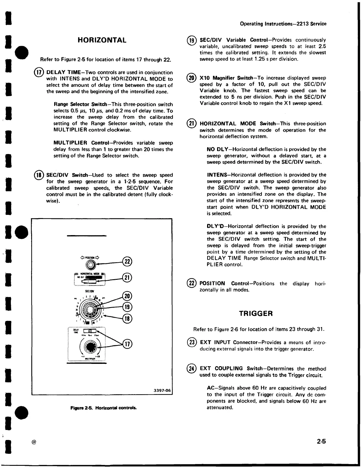
Refer to Figure 2-5 for location of items 17 through 22.
M7) DELAY TIME —Two controls are used in conjunction
with INTENS and DLY'D HORIZONTAL MODE to
select the amount of delay time between the start of
the sweep and the beginning of the intensified zone.
Range Selector Switch—This three-position switch
selects 0.5 /is, 10 /is, and 0.2 ms of delay time. To
increase the sweep delay from the calibrated
setting of the Range Selector switch, rotate the
MULTIPLIER control clockwise.
MULTIPLIER Control—Provides variable sweep
delay from less than 1 to greater than 20 times the
setting of the Range Selector switch.
(j? ) SEC/DIV Switch —Used to select the sweep speed
for the sweep generator in a 1-2-5 sequence. For
calibrated sweep speeds, the SEC/DIV Variable
control must be in the calibrated detent (fully clock
wise).
(jg ) SEC/DIV Variable Control—Provides continuously
variable, uncalibrated sweep speeds to at least 2.5
times the calibrated setting. It extends the slowest
sweep speed to at least 1.25 s per division.
(20) X10 Magnifier Switch—To increase displayed sweep
speed by a factor of 10, pull out the SEC/DIV
Variable knob. The fastest sweep speed can be
extended to 5 ns per division. Push in the SEC/DIV
Variable control knob to regain the X I sweep speed.
( 2?) HORIZONTAL MODE Switch—This three-position
switch determines the mode of operation for the
horizontal deflection system.
NO DLY—Horizontal deflection is provided by the
sweep generator, without a delayed start, at a
sweep speed determined by the SEC/DIV switch.
INTENS—Horizontal deflection is provided by the
sweep generator at a sweep speed determined by
the SEC/DIV switch. The sweep generator also
provides an intensified zone on the display. The
start of the intensified zone represents the sweep-
start point when DLY'D HORIZONTAL MODE
is selected.
DLY'D—Horizontal deflection is provided by the
sweep generator at a sweep speed determined by
the SEC/DIV switch setting. The start of the
sweep is delayed from the initial sweep-trigger
point by a time determined by the setting of the
DELAY TIME Range Selector switch and MULTI
PLIER control.
(2 ^ POSITION Control—Positions the display hori
zontally in all modes.
TRIGGER
Refer to Figure 2-6 for location of items 23 through 31.
(23) EXT INPUT Connector—Provides a means of intro
ducing external signals into the trigger generator.
(24) EXT COUPLING Switch—Determines the method
used to couple external signals to the Trigger circuit.
AC—Signals above 60 Hz are capacitively coupled
to the input of the Trigger circuit. Any dc com
ponents are blocked, and signals below 60 Hz are
attenuated.
@
2-5
Figure 2 -5. Horizontal controls.
 Loading...


