Theory of Operation—2213 Service
capacitor at a constant value. When a capacitor is charged
in this manner, the rise of voltage across the capacitor is
linear rather than exponential.
Field-effect transistors Q630A and Q630B are matched
devices. As such, the lDSS (drain current with gate-to-
source shorted) characteristics of each are nearly identical.
FET Q630B acts as a source-current supply for Q630A
and holds the gate-to-source voltage of Q630B at zero volts.
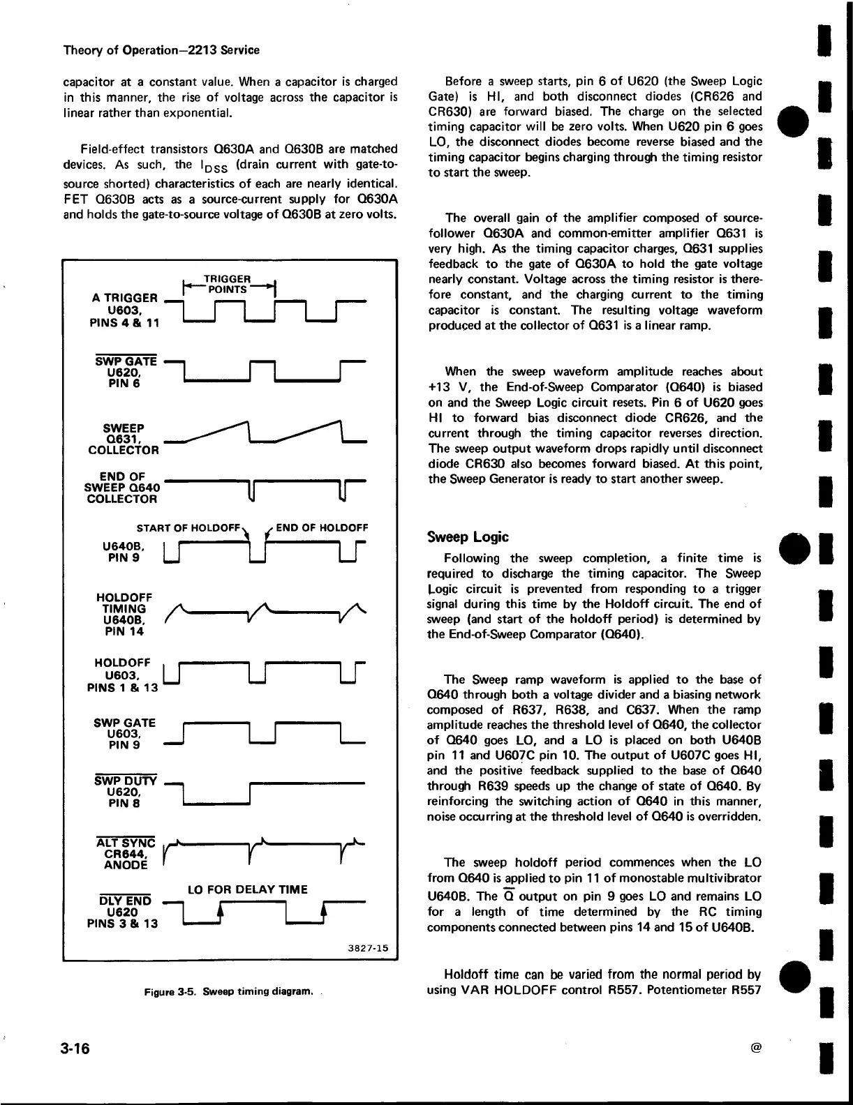
Figure 3-5. Sweep timing diagram.
Before a sweep starts, pin 6 of U620 (the Sweep Logic
Gate) is HI, and both disconnect diodes (CR626 and
CR630) are forward biased. The charge on the selected
timing capacitor will be zero volts. When U620 pin 6 goes
LO, the disconnect diodes become reverse biased and the
timing capacitor begins charging through the timing resistor
to start the sweep.
The overall gain of the amplifier composed of source-
follower Q630A and common-emitter amplifier Q631 is
very high. As the timing capacitor charges, Q631 supplies
feedback to the gate of Q630A to hold the gate voltage
nearly constant. Voltage across the timing resistor is there
fore constant, and the charging current to the timing
capacitor is constant. The resulting voltage waveform
produced at the collector of Q631 is a linear ramp.
When the sweep waveform amplitude reaches about
+13 V, the End-of-Sweep Comparator (Q640) is biased
on and the Sweep Logic circuit resets. Pin 6 of U620 goes
HI to forward bias disconnect diode CR626, and the
current through the timing capacitor reverses direction.
The sweep output waveform drops rapidly until disconnect
diode CR630 also becomes forward biased. At this point,
the Sweep Generator is ready to start another sweep.
Sweep Logic
Following the sweep completion, a finite time is
required to discharge the timing capacitor. The Sweep
Logic circuit is prevented from responding to a trigger
signal during this time by the Holdoff circuit. The end of
sweep (and start of the holdoff period) is determined by
the End-of-Sweep Comparator (Q640).
The Sweep ramp waveform is applied to the base of
Q640 through both a voltage divider and a biasing network
composed of R637, R638, and C637. When the ramp
amplitude reaches the threshold level of Q640, the collector
of Q640 goes LO, and a LO is placed on both U640B
pin 11 and U607C pin 10. The output of U607C goes HI,
and the positive feedback supplied to the base of Q640
through R639 speeds up the change of state of Q640. By
reinforcing the switching action of Q640 in this manner,
noise occurring at the threshold level of Q640 is overridden.
The sweep holdoff period commences when the LO
from Q640 is applied to pin 11 of monostable multivibrator
U640B. The Q output on pin 9 goes LO and remains LO
for a length of time determined by the RC timing
components connected between pins 14 and 15 of U640B.
Holdoff time can be varied from the normal period by
using VAR HOLDOFF control R557. Potentiometer R557
3-16
@
 Loading...


