Theory of Operation— 2213 Service
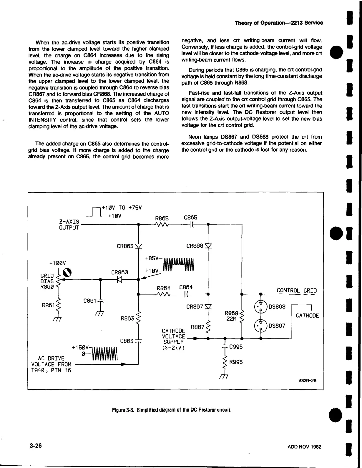
When the ac-drive voltage starts its positive transition
from the lower clamped level toward the higher clamped
level, the charge on C864 increases due to the rising
voltage. The increase in charge acquired by C864 is
proportional to the amplitude of the positive transition.
When the ac-drive voltage starts its negative transition from
the upper clamped level to the lower clamped level, the
negative transition is coupled through C864 to reverse bias
CR867 and to forward bias CR868. The increased charge of
C864 is then transferred to C865 as C864 discharges
toward the Z-Axis output level. The amount of charge that is
transferred is proportional to the setting of the AUTO
INTENSITY control, since that control sets the lower
clamping level of the ac-drive voltage.
The added charge on C865 also determines the control-
grid bias voltage. If more charge is added to the charge
already present on C865, the control grid becomes more
negative, and less crt writing-beam current will flow.
Conversely, if less charge is added, the control-grid voltage
level will be closer to the cathode-voltage level, and more crt
writing-beam current flows.
During periods that C865 is charging, the crt control-grid
voltage is held constant by the long time-constant discharge
path of C865 through R868.
Fast-rise and fast-fall transitions of the Z-Axis output
signal are coupled to the crt control grid through C865. The
fast transitions start the crt writing-beam current toward the
new intensity level. The DC Restorer output level then
follows the Z-Axis output-voltage level to set the new bias
voltage for the crt control grid.
Neon lamps DS867 and DS868 protect the crt from
excessive grid-to-cathode voltage if the potential on either
the control grid or the cathode is lost for any reason.
3-26
ADD NOV 1982
Figure 3-8. Simplified diagram of the DC Restorer circuit.
 Loading...


