Performance Check Procedure—2213 Service
VERTICAL
Equipment Required (see Table 4-1):
Calibration Generator (Item 1)
50-J2 BNC Termination (Item 5)
Leveled Sine-Wave Generator (Item 2)
Dual-Input Coupler (Item 6)
50-ft BNC Cable (Item 4)
4
INITIAL CONTROL SETTINGS
POWER
CRT
AUTO INTENSITY
AUTO FOCUS
Vertical
POSITION (both)
VERTICAL MODE
CH 1 VOLTS/DIV
CH 2 VOLTS/DIV
VOLTS/DIV Variable
(both)
INVERT
AC-GND-DC (both)
Horizontal
POSITION
HORIZONTAL MODE
SEC/DIV
SEC/DIV Variable
X10 Magnifier
Trigger
VAR H04.DOFF
MODE
SLOPE
LEVEL
I NT
SOURCE
ON (button in)
As desired
Best focused display
Midrange
CH 1
2 mV
10 V
CAL detent
Normal (button out)
DC
Midrange
NO DLY
0.5 ms
CAL detent
Off (knob in)
NORM
AUTO
J~
Midrange
VERT MODE
I NT
PROCEDURE STEPS
1. Check Deflection Accuracy and Variable Range
a. Connect a 10-mV standard-amplitude signal to the
CH 1 OR X input connector using a 50-J2 cable.
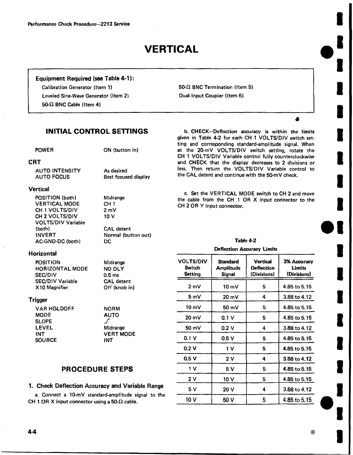
b. CHECK—Deflection accuracy is within the limits
given in Table 4-2 for each CH 1 VOLTS/DIV switch set
ting and corresponding standard-amplitude signal. When
at the 20-mV VOLTS/DIV switch setting, rotate the
CH 1 VOLTS/DIV Variable control fully counterclockwise
and CHECK that the display decreases to 2 divisions or
less. Then return the VOLTS/DIV Variable control to
the CAL detent and continue with the 50-mV check.
c. Set the VERTICAL MODE switch to CH 2 and move
the cable from the CH 1 OR X input connector to the
CH 2 OR Y input connector.
Table 4-2
Deflection Accuracy Limits
VOLTS/DIV
Switch
Setting
Standard
Amplitude
Signal
Vertical
Deflection
(Divisions)
3% Accuracy
Limits
(Divisions)
2 mV
10 mV
5
4.85 to 5.15
5 mV
20 mV
4
3.88 to 4.12
10 mV
50 mV
5 4.85 to 5.15
20 mV
0.1 V
5 4.85 to 5.15
50 mV
0.2 V
4
3.88 to 4.12
0.1 V
0.5 V 5 4.85 to 5.15
0.2 V
1 V
5
4.85 to 5.15
0.5 V
2 V 4 3.88 to 4.12
1 V
5 V
5 4.85 to 5.15
2 V
10 V
5 4.85 to 5.15
5 V
20 V
4
3.88 to 4.12
10 V
50 V 5
4.85 to 5.15
4-4
 Loading...


