Performance Check Procedure—2213 Service
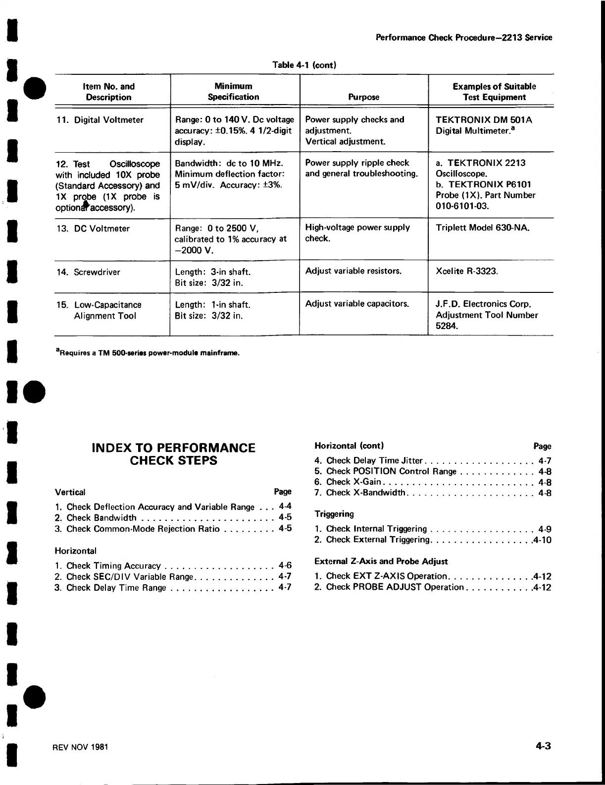
Table 4-1 (cont)
Item No. and
Description
Minimum
Specification
Purpose
Examples of Suitable
Test Equipment
11. Digital Voltmeter
Range: 0 to 140 V. Dc voltage
accuracy: ±0.15%. 4 1/2-digit
display.
Power supply checks and
adjustment.
Vertical adjustment.
TEKTRONIX DM 501A
Digital Multimeter.3
12. Test Oscilloscope
with included 10X probe
(Standard Accessory) and
IX probe (IX probe is
optiondraccessory).
Bandwidth: dcto 10 MHz.
Minimum deflection factor:
5 mV/div. Accuracy: ±3%.
Power supply ripple check
and general troubleshooting.
a. TEKTRONIX 2213
Oscilloscope.
b. TEKTRONIX P6101
Probe (IX ). Part Number
010-6101-03.
13. DC Voltmeter
Range: 0 to 2500 V,
calibrated to 1% accuracy at
-2000 V.
High-voltage power supply
check.
Triplett Model 630-NA.
14. Screwdriver
Length: 3-in shaft.
Bit size: 3/32 in.
Adjust variable resistors.
Xcelite R-3323.
15. Low-Capacitance
Alignment Tool
Length: 1-in shaft.
Bit size: 3/32 in.
Adjust variable capacitors.
J.F.D. Electronics Corp.
Adjustment Tool Number
5284.
aRequires a TM 500-series power-module mainframe.
INDEX TO PERFORMANCE
CHECK STEPS
Vertical Page
1. Check Deflection Accuracy and Variable Range . . . 4-4
2. Check Bandwidth
..........................................................
4-5
3. Check Common-Mode Rejection R atio
......................
4-5
Horizontal
1. Check Timing Accuracy
................................................
4-6
2. Check SEC/DIV Variable Range....................................4-7
3. Check Delay Time Range..............................................4-7
Horizontal (cont) Page
4. Check Delay Time Jitter
................................................
4-7
5. Check POSITION Control Range
.................................
4-8
6. Check X-Gain
..................................................................
4-8
7. Check X-Bandwidth........................................................4-8
Triggering
1. Check Internal Triggering..............................................4-9
2. Check External Triggering............................................4-10
External Z-Axis and Probe Adjust
1. Check EXT Z-AXIS Operation
....................................
4-12
2. Check PROBE ADJUST Operation
............................
4-12
REV NOV 1981
4-3
 Loading...


