Performance Check Procedure—2213 Service
Table 4-4
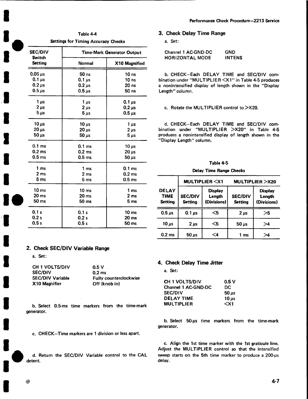
Settings for Timing Accuracy Checks
SEC/DIV
Switch
Setting
Time-Mark Generator Output
Normal
X I0 Magnified
0.05 ms
50 ns
10 ns
0.1 ms
0.1 ms 10 ns
0.2 ms
0.2 ms
20 ns
0.5 ms
0.5 ms
50 ns
1 ms
1 ms
0.1 ms
2 ms
2 ms
0.2 ms
5 ms
5 ms 0.5 ms
10ms
10 ms
1 ms
20 ms
20 ms
2 ms
50 ms
50 ms
5 ms
0.1 ms
0.1 ms
10 ms
0.2 ms
0.2 ms
20 ms
0.5 ms
0.5 ms
50 ms
1 ms
1 ms 0.1 ms
2 ms
2 ms 0.2 ms
5 ms
5 ms
0.5 ms
10 ms
10 ms 1 ms
20 ms
20 ms 2 ms
50 ms
50 ms
5 ms
0.1 s
0.1 s
10 ms
0.2 s
0.2 s
20 ms
0.5 s
0.5 s 50 ms
2. Check SEC/DIV Variable Range
a. Set:
CH 1 VOLTS/DIV
SEC/DIV
SEC/DIV Variable
X10 Magnifier
0.5 V
0.2 ms
Fully counterclockwise
O ff (knob in)
b. Select 0.5-ms time markers from the time-mark
generator.
c. CHECK—Time markers are 1 division or less apart.
d. Return the SEC/DIV Variable control to the CAL
detent.
3. Check Delay Time Range
a. Set:
Channel 1 AC-GND-DC GND
HORIZONTAL MODE INTENS
b. CHECK-Each DELAY TIME and SEC/DIV com
bination under "MULTIPLIER < X 1 " in Table 4-5 produces
a nonintensified display of length shown in the "Display
Length" column.
c. Rotate the MULTIPLIER control to >X20.
d. CHECK-Each DELAY TIME and SEC/DIV com
bination under "MULTIPLIER >X 20" in Table 4-5
produces a nonintensified display of length shown in the
"Display Length" column.
Table 4-5
Delay Time Range Checks
MULTIPLIER <X1
MULTIPLIER >X20
DELAY
TIME
Setting
SEC/DIV
Setting
Display
Length
(Divisions)
SEC/DIV
Setting
Display
Length
(Divisions)
0.5 ms
0.1 ms
<5
2 ms
>5
10 ms 2 ms
<5
50 ms
>4
0.2 ms
50 ms
<4
1 ms
>4
4. Check Delay Time Jitter
a. Set:
CH 1 VOLTS/DIV 0.5 V
Channel 1 AC-GND-DC DC
SEC/DIV 50 ps
DELAY TIME 10 MS
MULTIPLIER <X1
b . Select 5 0 - m s time markers from the time-mark
generator.
c. Align the 1st time marker with the 1st graticule line.
Adjust the MULTIPLIER control so that the intensified
sweep starts on the 5th time marker to produce a 2 0 0 -m s
delay.
@
4-7
 Loading...


