DELAYED-SWEEP MAGNIFICATION
Operating Procedures— 2213A Operators
The delayed-sweep feature of the 2213A can be used to
provide higher apparent magnification than is provided by
the X I0 Magnifier switch. Apparent magnification occurs as
a result of displaying a selected portion of the trace
(INTENS HORIZONTAL MODE) at a faster sweep speed
(DLY’D HORIZONTAL MODE).
When INTENS HORIZONTAL MODE is selected, the in
tensified zone indicates both the location and the start of
the sweep that will be displayed in DLY’D HORIZONTAL
MODE. Positioning of the intensified zone (i.e., setting the
amount of time between start of the sweep and start of the
intensified zone) is accomplished with the MULTIPLIER
control and the DELAY TIME Range Selector switch. At
higher sweep speeds the delay time can be adjusted to al
low the starting point of the intensified zone to occur past
the end of the display.
With either INTENS or DLY’D HORIZONTAL MODE se
lected, the DELAY TIME Range Selector switch and the
MULTIPLIER control provide continuously variable position
ing of the start of the delayed sweep. The DELAY TIME
Range Selector switch allows the start of the intensified
zone to be placed near the point of interest, while the
MULTIPLIER control provides fine adjustment of the inten-
sified zone.
When viewing aperiodic signals (such as complex digital
waveforms) with DLY’D HORIZONTAL MODE selected, the
start of the sweep may not be at the same point as the start
of the intensified zone. It may be necessary to connect a
reference signal from the system under test to the EXT
INPUT connector and to adjust VAR HOLDOFF control to
ensure correct display of the selected portion of the
waveform.
Using delayed-sweep magnification may produce a dis
play with some slight horizontal movement (pulse jitter).
Pulse jitter includes not only the inherent uncertainty of trig
gering the delayed sweep at exactly the same trigger point
each time, but also jitter that may be present in the input
signal.
The following procedure explains how to operate the de
layed-sweep feature and to determine the resulting appar
ent magnification factor.
1. Preset instrument controls and obtain a baseline
trace.
2. Apply the signal to either vertical channel input con-
j
nector and set the VERTICAL MODE switch to display the
channel used.
3. Set the appropriate VOLTS/DIV switch to produce a
display of approximately 5 divisions in amplitude and center
the display.
4. Set the SEC/DIV switch to a sweep speed which dis
plays at least one complete waveform cycle. 1
t
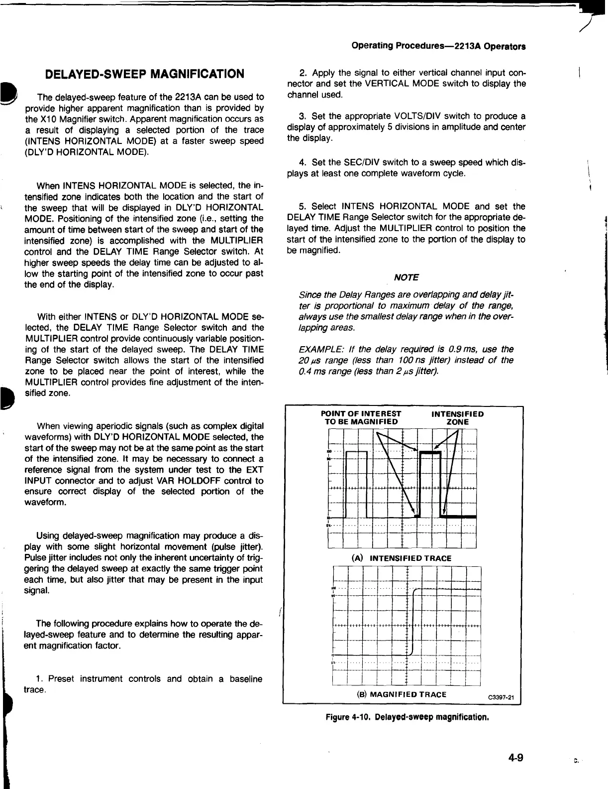
5. Select INTENS HORIZONTAL MODE and set the
DELAY TIME Range Selector switch for the appropriate de- j
layed time. Adjust the MULTIPLIER control to position the 1
start of the intensified zone to the portion of the display to
be magnified.
NOTE
Since the Delay Ranges are overlapping and delay jit
te r is proportional to maximum delay o f the range,
always use the sm allest delay range when in the over
lapping areas.
EXAMPLE: I f the delay required is 0.9 ms, use the
20 ms range (less than 100 ns jitte r) instead o f the
0.4 ms range (less than 2 ms jitte r).
POINT OF INTEREST INTENSIFIED
TO BE MAG NIFIED ZONE
n
1
-
-
-
-
1
(B) M AGNIFIED TRACE
Figure 4-10. Delayed-sweep magnification.
4-9
c.
 Loading...


