Performance Check Procedure—2213 Service
h. Set the generator output to produce a 1.5-division,
60-MHz display.
i. Repeat part d.
j. Move the generator output from the CH 2 OR Y
input connector to the CH 1 OR X input connector. Set
VERTICAL MODE to CH 1.
k. Repeat part d.
2. Check External Triggering
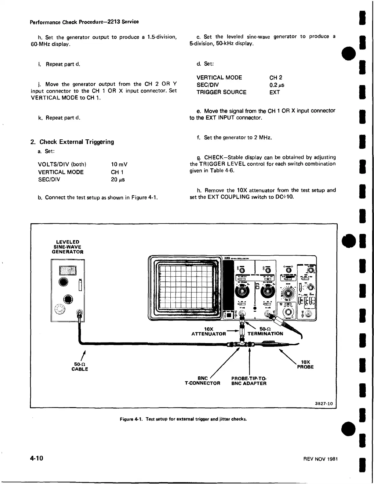
a. Set:
VOLTS/DIV (both) 10 mV
VERTICAL MODE CH 1
SEC/DIV 20 ns
b. Connect the test setup as shown in Figure 4-1.
c. Set the leveled sine-wave generator to produce a
5-division, 50-kHz display.
d. Set:
VERTICAL MODE CH 2
SEC/DIV 0.2 ms
TRIGGER SOURCE EXT
e. Move the signal from the CH 1 OR X input connector
to the EXT INPUT connector.
f. Set the generator to 2 MHz.
g. CHECK—Stable display can be obtained by adjusting
the TRIGGER LEVEL control for each switch combination
given in Table 4-6.
h. Remove the 10X attenuator from the test setup and
set the EXT COUPLING switch to DC^-10.
LEVELED
SINE-WAVE
GENERATOR
/
5o-n
CABLE
BNC
T-CONNECTOR
PROBE-TIP-TO-
BNC ADAPTER
10X
PROBE
3827-10
Figure 4-1. Test setup for external trigger and jitter checks.
4-10
REV NOV 1981
 Loading...


