Adjustment Procedure—2213 Service
2. Adjust Attenuator Step Balance
(R138 and R238)
a. Set both AC-GND-DC switches to GND.
b. Set the CH 1 VOLTS/DIV switch to 10 mV and
position the trace on the center horizontal graticule line
using the Channel 1 POSITION control.
c. Change the CH 1 VOLTS/DIV switch to 2 mV.
d. ADJUST—Ch 1 Step Bal (R138) to set the trace on
the center horizontal graticule line.
e. Repeat parts b through d until there is no trace shift
when changing the CH 1 VOLTS/DIV switch from 10 mV
to 2 mV.
f. Change the VERTICAL MODE switch to CH 2.
g. Repeat parts b through e for Channel 2, adjusting
Ch 2 Step Bal (R238) in step d.
3. Adjust A ttenuator X 1 0 Balance
(R 146 and R246)
a. Set the CH 2 VOLTS/DIV switch to 20 mV.
b. Position the trace on the center horizontal graticule
line using the Channel 2 POSITION control.
c. Change the CH 2 VOLTS/DIV switch to 10 mV.
d. ADJUST—Ch 2 X10 Bal (R246) to set the trace on
the center horizontal graticule line.
e. Repeat parts a through d until there is no trace shift
when changing the CH 2 VOLTS/DIV switch from 20 mV
to 10 mV.
f. Change the VERTICAL MODE switch to CH 1.
g. Repeat parts a through e for Channel 1, adjusting
Ch 1 XIOBal (R146) in step d.
4. Check Deflection Accuracy and Variable Range
a. Set:
CH 1 VOLTS/DIV 2 mV
CH 2 VOLTS/DIV 10 V
AC-GND-DC (both) DC
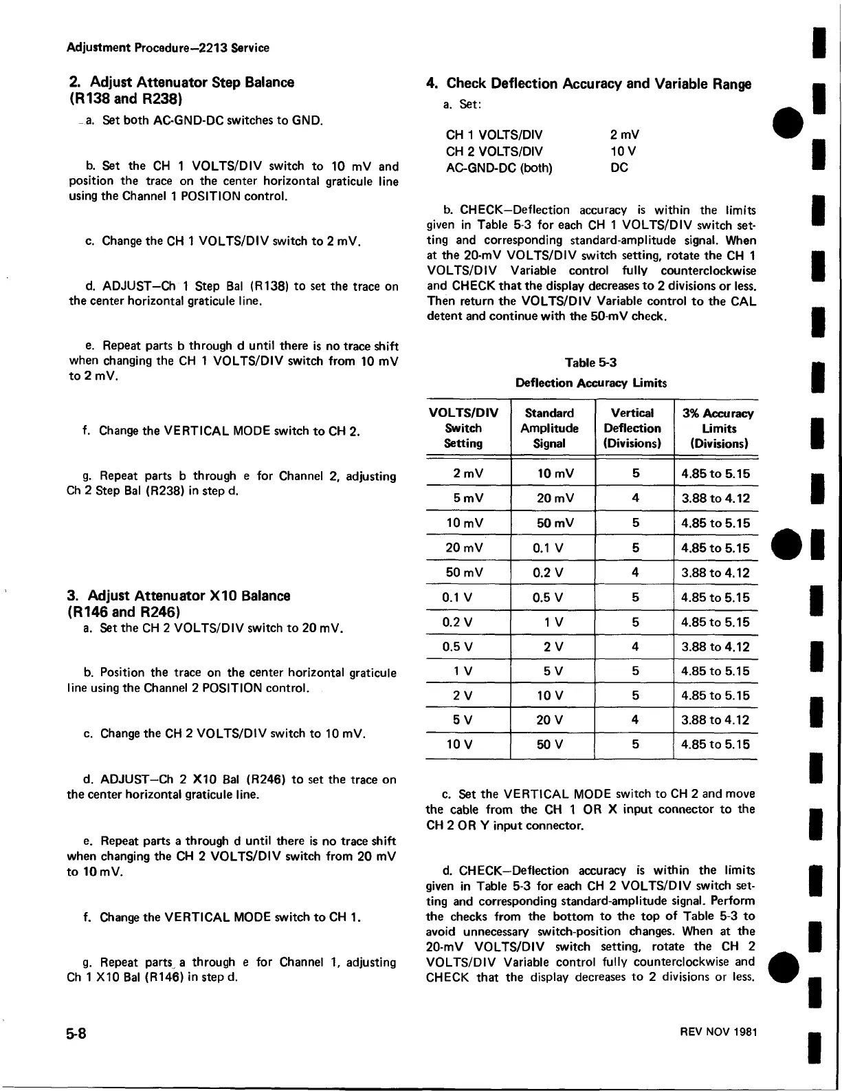
b. CHECK—Deflection accuracy is within the limits
given in Table 5-3 for each CH 1 VOLTS/DIV switch set
ting and corresponding standard-amplitude signal. When
at the 20-mV VOLTS/DIV switch setting, rotate the CH 1
VOLTS/DIV Variable control fully counterclockwise
and CHECK that the display decreases to 2 divisions or less.
Then return the VOLTS/DIV Variable control to the CAL
detent and continue with the 50-mV check.
Table 5-3
Deflection Accuracy Limits
VOLTS/DIV
Switch
Setting
Standard
Amplitude
Signal
Vertical
Deflection
(Divisions)
3% Accuracy
Limits
(Divisions)
2 mV 10 mV
5
4.85 to 5.15
5 mV 20 mV
4
3.88 to 4.12
10 mV
50 mV 5
4.85 to 5.15
20 mV
0.1 V
5
4.85 to 5.15
50 mV
0.2 V
4
3.88 to 4.12
0.1 V 0.5 V
5
4.85 to 5.15
0.2 V 1 V 5 4.85 to 5.15
0.5 V 2 V
4
3.88 to 4.12
1 V 5 V
5
4.85 to 5.15
2 V
10 V 5
4.85 to 5.15
5 V
20 V
4
3.88 to 4.12
10 V
50 V
5
4.85 to 5.15
c. Set the VERTICAL MODE switch to CH 2 and move
the cable from the CH 1 OR X input connector to the
CH 2 OR Y input connector.
d. CHECK—Deflection accuracy is within the limits
given in Table 5-3 for each CH 2 VOLTS/DIV switch set
ting and corresponding standard-amplitude signal. Perform
the checks from the bottom to the top of Table 5-3 to
avoid unnecessary switch-position changes. When at the
20-mV VOLTS/DIV switch setting, rotate the CH 2
VOLTS/DIV Variable control fully counterclockwise and
CHECK that the display decreases to 2 divisions or less.
5-8
REV NOV 1981
 Loading...


