e. Disconnect the test setup.
Adjustment Procedure—2213 Service
10. Adjust Attenuator Compensation (C105,
C104, C l 11, C l 10, C205, C204, C 211, and C210)
a. Set:
CH 1 VOLTS/DIV 20 mV
AC-GND-DC (both) DC
SEC/DIV 0.2 ms
b. Connect a 1-kHz, high-amplitude square wave via a
50-J2 termination, a probe-tip-to-bnc adapter, and a P6120
Probe to the CH 1 OR X input connector.
c. Set the generator output to produce a 5-division
display and compensate the probe using the probe com
pensation adjustment (see the probe instruction manual).
d. Set the CH 1 VOLTS/DIV switch to 0.2 V.
e. Replace the probe and probe-tip-to-bnc adapter with
a 50-f2 cable.
f. Adjust the generator output for a 5-division display.
NOTE
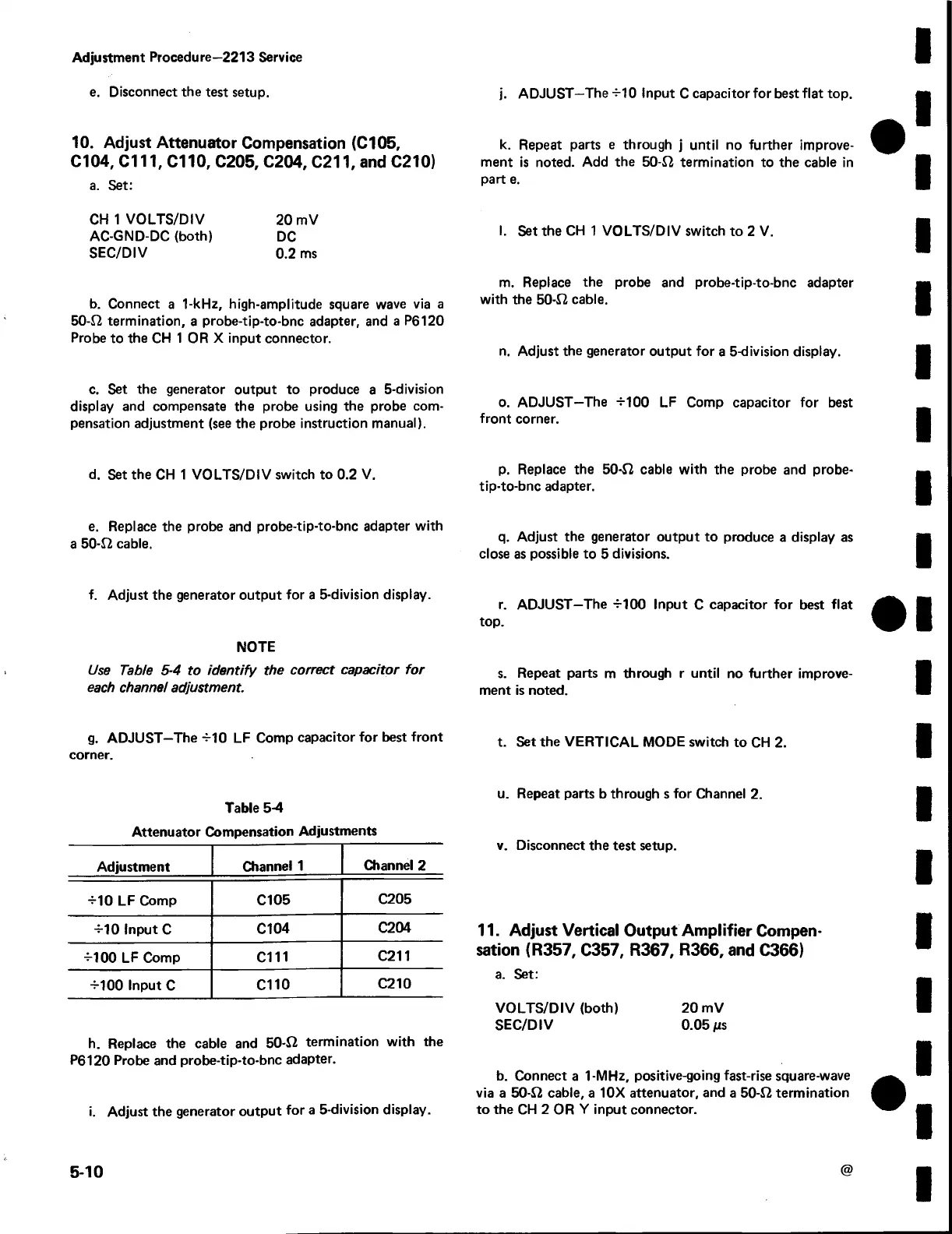
Use Table 5-4 to id e n tify the correct capacitor fo r
each channel adjustment.
g. ADJUST—The-M0 LF Comp capacitor for best front
corner.
Table 5-4
Attenuator Compensation Adjustments
Adjustment
Channel 1
Channel 2
M 0 LF Comp
Cl 05
C205
-M0 Input C
C104
C204
-M00 LF Comp cm
C211
-M00 Input C
Clio
C210
h. Replace the cable and 50-J2 termination with the
P6120 Probe and probe-tip-to-bnc adapter.
i. Adjust the generator output for a 5-division display.
j. ADJUST—The-M0 Input C capacitor for best flat top.
k. Repeat parts e through j until no further improve
ment is noted. Add the 50-J2 termination to the cable in
part e.
I. Set the CH 1 VOLTS/DIV switch to 2 V.
m. Replace the probe and probe-tip-to-bnc adapter
with the 50-12 cable.
n. Adjust the generator output for a 5-division display.
o. ADJUST—The -M00 LF Comp capacitor for best
front corner.
p. Replace the 50-J2 cable with the probe and probe-
tip-to-bnc adapter.
q. Adjust the generator output to produce a display as
close as possible to 5 divisions.
r. ADJUST—The -M00 Input C capacitor for best flat
top.
s. Repeat parts m through r until no further improve
ment is noted.
t. Set the VERTICAL MODE switch to CH 2.
u. Repeat parts b through s for Channel 2.
v. Disconnect the test setup.
11. Adjust Vertical O utput A m plifier Compen
sation (R 357, C357, R 367, R 366, and C366)
a. Set:
VOLTS/DIV (both) 20 mV
SEC/DIV 0.05/is
b. Connect a 1-MHz, positive-going fast-rise square-wave
via a 50-S2 cable, a 10X attenuator, and a 50-S2 termination
to the CH 2 OR Y input connector.
5-10
 Loading...


