Maintenance—2213 Service
Troubleshooting Charts
The troubleshooting charts contained in the "Diagrams"
section are to be used as an aid in locating malfunctioning
circuitry. To use the charts, begin with the Troubleshooting
Guide. This chart will help identify a particular problem
area for further troubleshooting.
Note that some troubleshooting-procedure boxes on
each chart contain numbers along their lower edges. These
numbers identify the applicable schematic diagram(s) to
be used when performing the action specified in the box.
Both General and Specific notes may be called out in
the troubleshooting-chart boxes. These notes are located on
the inner panels of the foldout pages. Specific Notes
contain procedures or additional information to be used in
performing the particular troubleshooting step called for in
that box. General Notes contain information that pertains
to the overall troubleshooting procedure.
Some malfunctions, especially those involving multiple
simultaneous failures, may require more elaborate trouble
shooting approaches with references to circuit descriptions
in the "Theory of Operation" section of this manual.
Component Color Coding
Information regarding color codes and markings of
resistors and capacitors is located in the color-coding
illustration (Figure 9-1) at the beginning of the "Diagrams"
section.
RESISTOR COLOR CODE. Resistors used in this instru
ment are carbon-film, composition, or precision metal-film
types. They are color coded with the EIA color code;
however, some metal-film resistors may have the value
printed on the body. The color code is interpreted by
starting with the stripe that is nearest to one end of the
resistor. Composition resistors have four stripes; these
represent two significant figures, a multiplier, and a
tolerance value. Metal-film resistors have five stripes which
represent three significant figures, a multiplier, and a
tolerance value.
CAPACITOR MARKINGS. Capacitance values of
common disc capacitors and small electrolytics are marked
on the side of the capacitor body. White ceramic capacitors
are color coded in picofarads, using a modified EIA code.
Dipped tantalum capacitors are color coded in micro
farads. The color dot indicates both the positive lead and
the voltage rating. Since these capacitors are easily
destroyed by reversed or excessive voltage, be careful to
observe the polarity and voltage rating.
DIODE COLOR CODE. The cathode end of each glass-
encased diode is indicated by either a stripe, a series of
stripes, or a dot. For most silicon or germanium diodes
marked with a series of stripes, the color combination of
the stripes identifies three digits of the Tektronix Part
Number, using the resistor color-code system (e.g., a diode
having either a pink or a blue stripe at the cathode end,
then a brown-gray-green stripe combination, indicates
Tektronix Part Number 152-0185-00). The cathode and
anode ends of a metal-encased diode can be identified by
the diode symbol marked on its body.
Semiconductor Lead Configurations
Figure 9-2 in the "Diagrams" section shows the lead
configurations for semiconductor devices used in the
instrument. These lead configurations and case styles are
typical of those available at completion of the design of
the instrument. Vendor changes and performance improve
ment changes may result in changes of case styles or lead
configurations. If the device in question does not appear to
match the configuration in Figure 9-2, examine the
associated circuitry or consult a semiconductor manu
facturer's data sheet.
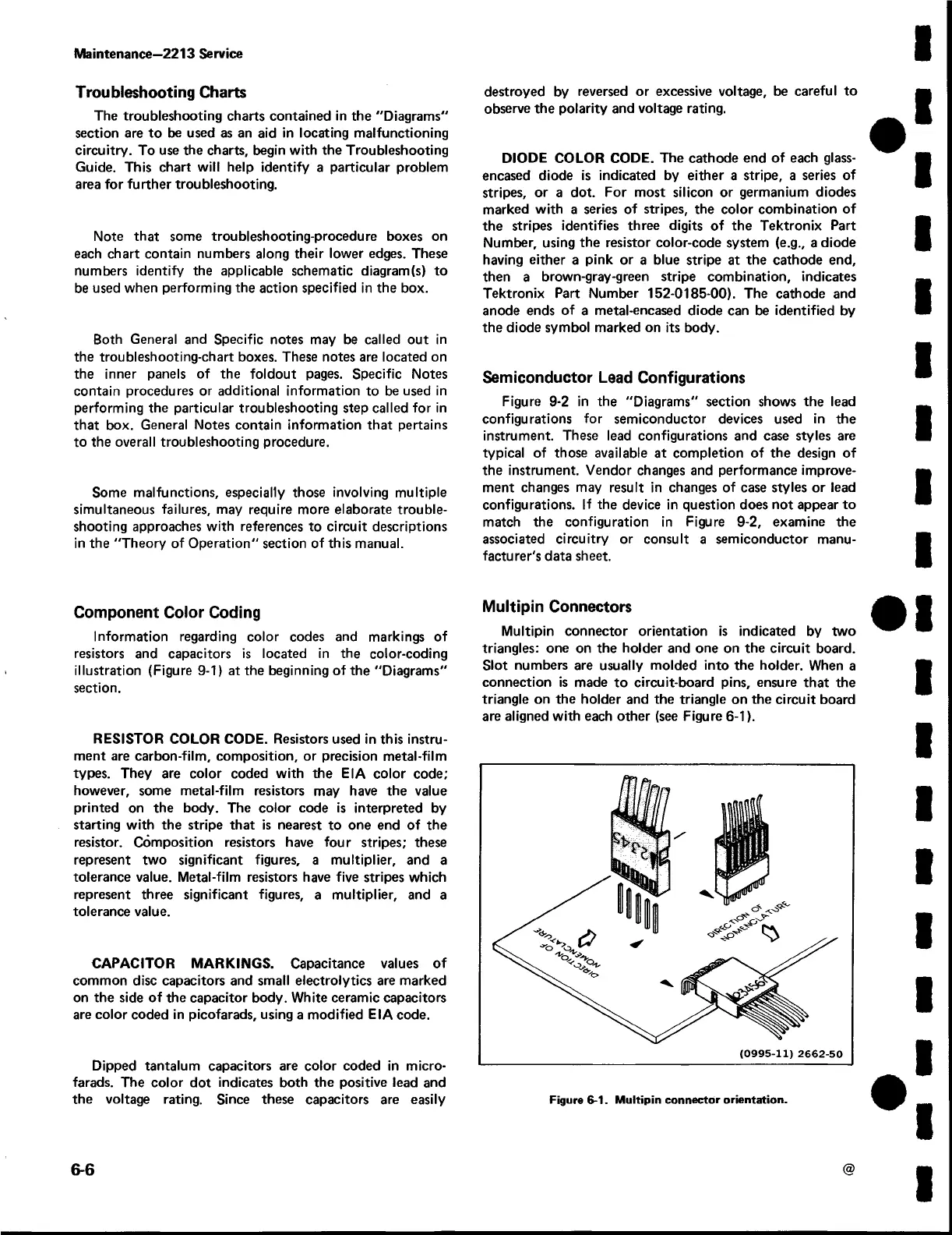
Multipin Connectors
Multipin connector orientation is indicated by two
triangles: one on the holder and one on the circuit board.
Slot numbers are usually molded into the holder. When a
connection is made to circuit-board pins, ensure that the
triangle on the holder and the triangle on the circuit board
are aligned with each other (see Figure 6-1).
(0995-11) 2662-50
6-6
@
Figure 6-1. Multipin connector orientation.
 Loading...


