Maintenance-2213 Service
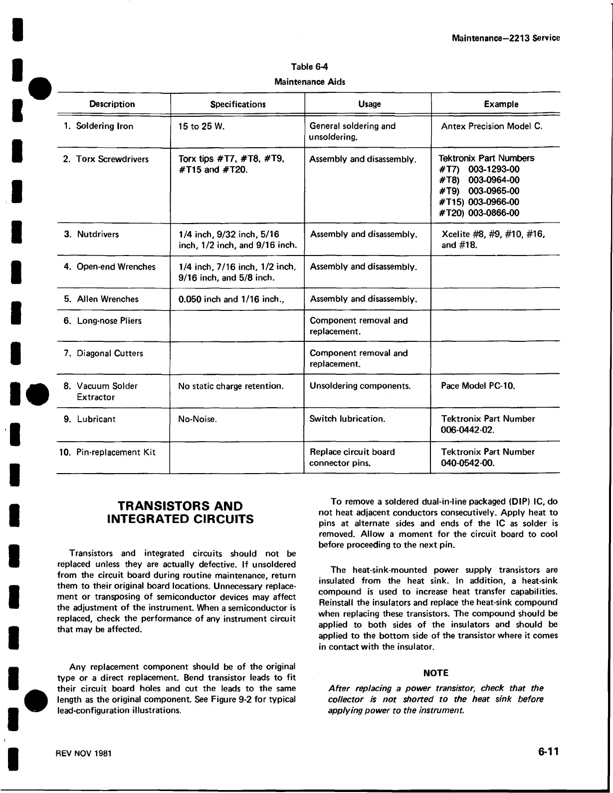
Table 6-4
Maintenance Aids
Description
Specifications
Usage
Example
1. Soldering Iron
15 to 25 W.
General soldering and
unsoldering.
Antex Precision Model C.
2. Torx Screwdrivers
Torx tips #T7, #T8, #T9,
#T15 and #T20.
Assembly and disassembly.
Tektronix Part Numbers
#T7) 003-1293-00
#T8) 003-0964-00
#T9) 003-0965-00
#T15) 003-0966-00
#T20) 003-0866-00
3. Nutdrivers 1/4 inch, 9/32 inch, 5/16
inch, 1/2 inch, and 9/16 inch.
Assembly and disassembly.
Xcelite #8, #9, #10, #16,
and #18.
4. Open-end Wrenches 1/4 inch, 7/16 inch, 1/2 inch,
9/16 inch, and 5/8 inch.
Assembly and disassembly.
5. Allen Wrenches 0.050 inch and 1/16 inch..
Assembly and disassembly.
6. Long-nose Pliers
Component removal and
replacement.
7. Diagonal Cutters
Component removal and
replacement.
8. Vacuum Solder
Extractor
No static charge retention.
Unsoldering components. Pace Model PC-10.
9. Lubricant No-Noise.
Switch lubrication. Tektronix Part Number
006-0442-02.
10. Pin-replacement Kit
Replace circuit board
connector pins.
Tektronix Part Number
040-0542-00.
TRANSISTORS AND
INTEGRATED CIRCUITS
Transistors and integrated circuits should not be
replaced unless they are actually defective. If unsoldered
from the circuit board during routine maintenance, return
them to their original board locations. Unnecessary replace
ment or transposing of semiconductor devices may affect
the adjustment of the instrument. When a semiconductor is
replaced, check the performance of any instrument circuit
that may be affected.
Any replacement component should be of the original
type or a direct replacement. Bend transistor leads to fit
their circuit board holes and cut the leads to the same
length as the original component. See Figure 9-2 for typical
lead-configuration illustrations.
To remove a soldered dual-in-line packaged (DIP) 1C, do
not heat adjacent conductors consecutively. Apply heat to
pins at alternate sides and ends of the 1C as solder is
removed. Allow a moment for the circuit board to cool
before proceeding to the next pin.
The heat-sink-mounted power supply transistors are
insulated from the heat sink. In addition, a heat-sink
compound is used to increase heat transfer capabilities.
Reinstall the insulators and replace the heat-sink compound
when replacing these transistors. The compound should be
applied to both sides of the insulators and should be
applied to the bottom side of the transistor where it comes
in contact with the insulator.
NOTE
After replacing a power transistor, check that the
collector is not shorted to the heat sink before
applying power to the instrument.
REV NOV 1981
6-11
 Loading...


