EasyManuals Logo
Home>Tektronix>Test Equipment>2213A

Tektronix 2213A Operator's Manual

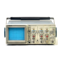
Tektronix 2213A
36 pages
To Next Page IconTo Next Page
To Previous Page IconTo Previous Page
Page #19 background imageLoading...
Page #19 background image
R
efer
to
2-6
for
location
of
items
23
t
h
ro
u
g
h
31
.
23
TR
IGG
ER
M
o
d
e
Switc
h
es-T
h
ree
sectio
n
switc
h
t
h
at
determi
n
es
t
h
e
trigger
mode
for
t
h
e
swee
p
.
N
O
RM
-Swee
p
is
i
n
itiated
w
hen an
adequate
tr
ig-
ger
signal
is
app
lied
.
In
t
h
eab
sence
of
α
trigger
sig
n
al,
no
baseline
trace
will
be
p
resent
.
Ρ
-
Ρ
A
U
TO-T
VL
I
NE
-
P
e
r
mits
triggering
on
wave-
forms
an
d
televisio
n
lines
h
aving
re
p
etition
rates
of
at
least
20
H
z
.
Sweep
free-runs
in
t
he a
b
sence
of
an
ade
q
uate
trigger
signal
or
w
hen
t
h
e
repetition
rate
is
b
elow
20
Hz
.
T
h
e
range
of
t
he
TR
IGG
ER
LEVEL
co
n
trol is
rest
r
icted
to
t
h
e
pea
k
-to-
peak
range
of
t
h
e
trigger
signal
.
TVF
I
EL
D-
P
ress
in
b
ot
h
Ρ
-
ΡA
U
TO
and
N
O
RM
b
uttons
.
P
ermits
triggering
on
television
fiel
d
sig-
n
als
.
TR
IGG
ER LEVEL
control
s
h
ould
b
e
rotated
fully
countercloc
kwise
w
hen
triggering
on
TV
sig-
nals
wit
h
negative
going
sync
and
cloc
kwise
for
p ositive
going
sync
.
SG
L
SWP
RE
SE
T-
P
ress
in
t
h
e sp
ring-ret
u
rn
but-
ton
momentarily
to
arm
t
h
e
trigger
circuit
for
α
sin-
gle-swee
p
dis
p
lay
.
In
t
h
is
mode,
t
h
e
trigger
system
operates
t
he
same
as
N
O
RM,
except
only
one
swee
p
is
dis
p
layed
for
eac
h
trigger
sig
n
al
.
Anot
h
er
swee
p
can
n
ot
b
e
dis
p
laye
d
u
n
til
t
he
SG
L
SWP
RE
SE
T
button
is
momentarily
pressed
in
agai
n
to
reset
t
he
trigge
r
circuit
.
T
h
is
mode
is
useful
for
dis-
playi
n
g
and
p
hotograph
ing
eit
h
er
non
r
e
p
etitive
sig-
n
als
or
signals
t
h
at
cause
u
nstable
conventional
,
.
dis
p
lays
(e .g
.,
signals
t h
at
vary
in
amplit
u
de,
sh
ap
e,
o
r
time)
.
24
T
R
IG'D-
RE
ADY
I
nd
icato
r
-
LE
D
illuminates
w
hen
ei-
t
h
er
Ρ
-
ΡAU
TO
or
N
O
RM
Trigger
M
ode
is
selected
and
t
he
Swee
p has
been
triggered
(T
R
IG'D)
.
In
single
swee
p
display,
t
he
LE
D
illuminates
to
indicate
t
h
at
t
h
e
Trigger
circuit
is
arme
d
(
RE
ADY)
.
ί 5
TR
IGG
ER
LEVEL
Co
n
t
r
ol-Selects
t
h
e
amplitude
p
oint
on
t
he
t
r
igge
r
signal
at
w
h
ic
h
t
h
e
swee
p
is
triggered
.
ίό
SL
O
PE
Switc
h
-Selects
t
h
e
slope
of
t h
e
sig
n
al
t
h
at
triggers
t
h
e
swee
p
.
O
U
T-
Wh
en
butto
n
is
released
out,
swee
p
is
trig-
gered from
t
h
e
p
ositive-goi
ng
slo
p
e
of
t
h
e
trigger
signal
.
IN-When
button
is
pressed
in,
swee
p
is
triggered
from
t
h
e
negative-going
slope
of
t
h
e
trigger
signal
.
2)
SO
UR
CE
Switch
-Determi
nes
t
he source
of
t
he
trig-
ger
sig
n
al
t
h
at
is
cou
p
led
to
t
he
i
np
ut
of
t h
e
trigger
circuit
.
ΙΝΤ
-
P
ermits
trigge
r
ing
on
sig
n
als
t
h
at
are
a
pp
lied
to
t
he
C
H
1
OR
Χ
and
C
H
2
OR
Υ
i
np
ut
connec-
tors
.
T
h
e
source
of
t
he
inter
n
al
signal
is
selecte
d
by
t
h
e
ΙΝΤ
switc
h
.
L
I
NE
-T
he
power-so
ur
ce
waveform
is
t
he source
of
t
he
trigger
signal
.
T
h
is
trigger
source
is
u
sef
u
l
w
hen
vertical
input
signals
a
r
e
time
related
(multi-
p
le
or
sub
m
u
lti
p
le)
to
t
he
f r
e
q
uency
of
t
he p
ower-
in
pu
t
source
voltage
.
ΕΧΤ
-
P
ermits
t
r
iggering
on
signals
app
lied
to
t
h
e
ΕΧΤ
I
NPU
T
connector
.
2$
ΙΝΤ
Switc
h
-Selects
t
he sou
rce
of
t
he
internal
trig-
gering
sig
n
al
w
hen
t
he
SOUR
C
E
switc
h
is
set
to
INT
.
CH
1-T
he
signal
applied
to
t
he
C
H
1
O
RΧ
in
p
ut
connector
is
t
he sou
rce
of
t
h
e
trigge
r
sig
n
al
.
VER
T
M
OD
E
-T
he
inte rn
al
trigger
source
is
deter-
mi
ne
d
by
t
he
signals
selected
for
d
is
p
lay
by
t
he
VER
TICA
L
M
OD
E
switc
hes
.
See
Table
2-1 for
VER
T
M
OD
E
trigger
source
.

Other manuals for Tektronix 2213A

Questions and Answers:

Question and Answer IconNeed help?

Do you have a question about the Tektronix 2213A and is the answer not in the manual?

Tektronix 2213A Specifications

General IconGeneral
BrandTektronix
Model2213A
CategoryTest Equipment
LanguageEnglish

Related product manuals