I
N
T
R
OD
U
CTIO
N
After
b
ecoming
familiar
with
t
he
capabilities
of
the
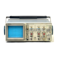
2213
Α
Oscilloscope
an
operator
can
then
easily
develop conve-
nient
methods
for
making
p articular
measurements
.
The
in-
formation
in
this
section
is
designed
to
enhance
operator
understanding
and
to
assist
in
developing
efficient
tech-
ni
q
ues
for
making
specific
measurements
.
Recommended
methods
for
making
basic
measurements
with
your
instru-
ment
are
described
in
the
procedures
contained
in
t
his
section
.
When
α p
rocedure
first
calls
for
presetting
instrument
controls
and
obtaining
α
b
aseline
trace, refer
to
the
"Oper-
ator's
Adjustments"
p
art
in
Section
3
and
perform
steps
1
through
4
u
nder
"Baseline
Trace"
.
IN
D
E
X
TO
B
ASIC
A
PPL
ICATIO
N
PR
OC
E
D
URE
S
VOLTAGE
MEASUREMENTS
. . . . . . . . . . . . . . . . .
4-1
AC
Peak-to-Peak
Voltage
. . . . . . . . . . . . . . . . . .
4-1
Instantaneous
V
oltage
. . .
.
. . .
. .
. . . . . . . . . . . .
4-2
Algebraic
Addition
. .
. . . . .
. . . . . . . . . . . . . . . . . .
4-3
Common-Mode
Rejection
. .
. . . . .
. . . . . . . . . . . .
4-3
Amplitude
Comparison
. . . . . .
. . .
. . . . . . . . . . . .
4-4
TIME
MEASUREMENTS
. . . . . . . . .
.
. . . . . . . . . . .
4-4
Time
Duration
. . . . . . . . . . .
. . .
.
. . . . . . . . . . . . .
4-4
Frequency
. . . . . . . . . . . . . . . . . . . .
. . . .
. . . . . . .
4-5
Rise
Time
. . . . . . . . . . . . . . . . . . . . . . . . . . . . . . .
4-5
Time
Difference
B
etween
Pulses
On
Time
Related
Signals
. . . . . . . . . . . . . . . .
. . . .
. . . . . . .
4-6
Phase
Difference
. . . . . . . . . . . . . . . . . .
.
.
. . . . .
4-7
TELEVISION
DISPLAYS
. . . . . . . . . . . . . . . . . .
.
. .
.
4-8
TV
Line Signal
. .
. . . . . . . . . . . . . . . .
. . . .
. . . . .
4-8
TV
Field
Signal
. . .
.
.
. . .
. . . . . .
. . . . . . . . . . . . .
4-8
DELAYED-SWEEP
MAGNIFICATION
. . . . .
. . . . .
. .
4-9
V
O
L
TAG
E
ME
AS
UREMEN
TS
AC
P
eak-to-Peak
Voltage
To
make
α
peak-to-peak voltage
measurement,
use
the
following
procedure
:
ΝΟΤΕ
Th
is
procedure
may
also
be used
to
ma
k
e
voltage
measu
r
ements
b
etween
any two
p
oints
on
t
he
waveform
.
1
.
Preset
instrument
controls
and
obtain
α
baseline
trace
.
2
.
Apply
t
he ac
signal
to
either
vertical-channel
in
p
ut
connector
and
set
the
VERTICAL
MODE
switch
to
display
the
channel
used
.
3
.
Set
the
appropriate
V
OLTS/DIV
switch
to
display
about
five
d ivisions
of
the
waveform,
ensuring
that
the
V
OLTS/DIV
Variable
control
is in
the
CAL
detent
.
4
.
Adjust the
TRIGGER
LEVEL
control
to obtain
α
stable
display
.
5
.
Set the
SEC/DIV
switch
to
α p
osition that
displays
several
cycles
of
the
waveform
.
6
.
V
ertically
position
the
d
isplay
so
that
the
negative
peak
of
the
waveform
coi
n
cides
with
one
of
the
h
orizontal
graticule
lines
(see
Figure
4-1,
P
oint
Α
)
.
7
.
Horizontally
position
the
dis
p
lay
so
that
one
of
the
p
ositive
peaks
coincides
with
t
he
center
vertical
graticule
line
(see Figure
4-1,
P
oint
Β
)
.
8
.
M
easure
the
vertical
d
eflection
from
p
eak-to-
p
eak
(see Figure
4-1,
Point
Α
to
P
oint
Β
)
.

 Loading...