Specification—2445 Operators
Table 1-1 (cont)
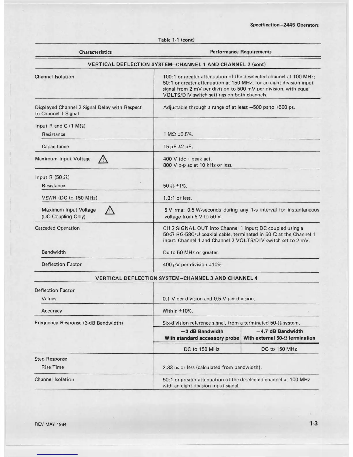
Characteristics Performance Requirements
VERTICAL DEFLECTION SYSTEM-CHANNEL 1 AND CHANNEL 2 (cont)
Channel Isolation
100:1 or greater attenuation of the deselected channel at 100 MHz;
50:1 or greater attenuation at 150 MHz, for an eight-division input
signal from 2 mV per division to 500 mV per division, with equal
VOLTS/DIV switch settings on both channels.
Displayed Channel 2 Signal Delay with Respect
to Channel 1 Signal
Adjustable through a range of at least —500 ps to +500 ps.
Input R and C (1 MO)
Resistance
1 MO ±0.5%.
Capacitance 15 pF ±2 pF.
Maximum Input Voltage
A
400 V (dc + peak ac).
800 V p-p ac at 10 kHz or less.
Input R (50 O)
Resistance
50 O ±1%.
VSWR (DC to 150 MHz)
1.3:1 or less.
Maximum Input Voltage
(DC Coupling Only)
A
5 V rms; 0.5 W-seconds during any 1-s interval for instantaneous
voltage from 5 V to 50 V.
Cascaded Operation
CH 2 SIGNAL OUT into Channel 1 input; DC coupled using a
50-0 RG-58C/U coaxial cable, terminated in 50 $7 at the Channel 1
input. Channel 1 and Channel 2 VOLTS/DIV switch set to 2 mV.
Bandwidth
Dc to 50 MHz or greater.
Deflection Factor
400 mV per division ±10%.
VERTICAL DEFLECTION SYSTEM-CHANNEL 3 AND CHANNEL 4
Deflection Factor
Values 0.1 V per division and 0.5 V per division.
Accuracy
Within ±10%.
Frequency Response (3-dB Bandwidth) Six-division reference signal, from a terminated 50-0 system.
— 3 dB Bandwidth
With standard accessory probe
— 4.7 dB Bandwidth
With external 50-0 termination
DC to 150 MHz
DC to 150 MHz
Step Response
Rise Time
2.33 ns or less (calculated from bandwidth).
Channel Isolation
50:1 or greater attenuation of the deselected channel at 100 MHz
with an eight-division input signal.
REV MAY 1984
1-3