Controls, Connectors, and Indicators—2445 Operators
( m ) MODE Switches—Select the indicated channel(s)
for display when latched in. Any combination of the
five possible signal selections can be displayed by
pressing in the appropriate push buttons. The Chan
nel 1 signal will be displayed if none of the MODE
switches are latched in.
The algebraic sum of Channel 1 and Channel 2 is
displayed when the ADD push button is latched in.
When both ADD and INVERT buttons are latched in,
the waveform displayed is the difference between the
Channel 1 and Channel 2 signals. The INVERT
button also inverts the polarity of the signal output
at the CH 2 SIG OUT connector on the rear panel.
At the same time, the Channel 2 trigger-signal
polarity is inverted so that if CH 2 is selected as the
TRIGGER SOURCE, the displayed slope will agree
with the TRIGGER SLOPE switch setting.
When multiple channels are selected, they are dis
played sequentially in order of priority. The estab
lished priority order is: C H I, CH 2, ADD, CH 3,
then CH 4.
The position of this switch has no effect on the
switching rate of multiple X-Y displays. When more
than one X-Y display is selected, switching occurs
at 2.5 MHz.
( n ) 2 0 MHz BW LIMIT Switch—Reduces upper 3 dB
bandpass of the vertical deflection system to a limit
of 13 to 24 MHz when latched in. Full instrument
bandwidth is available when push button is out.
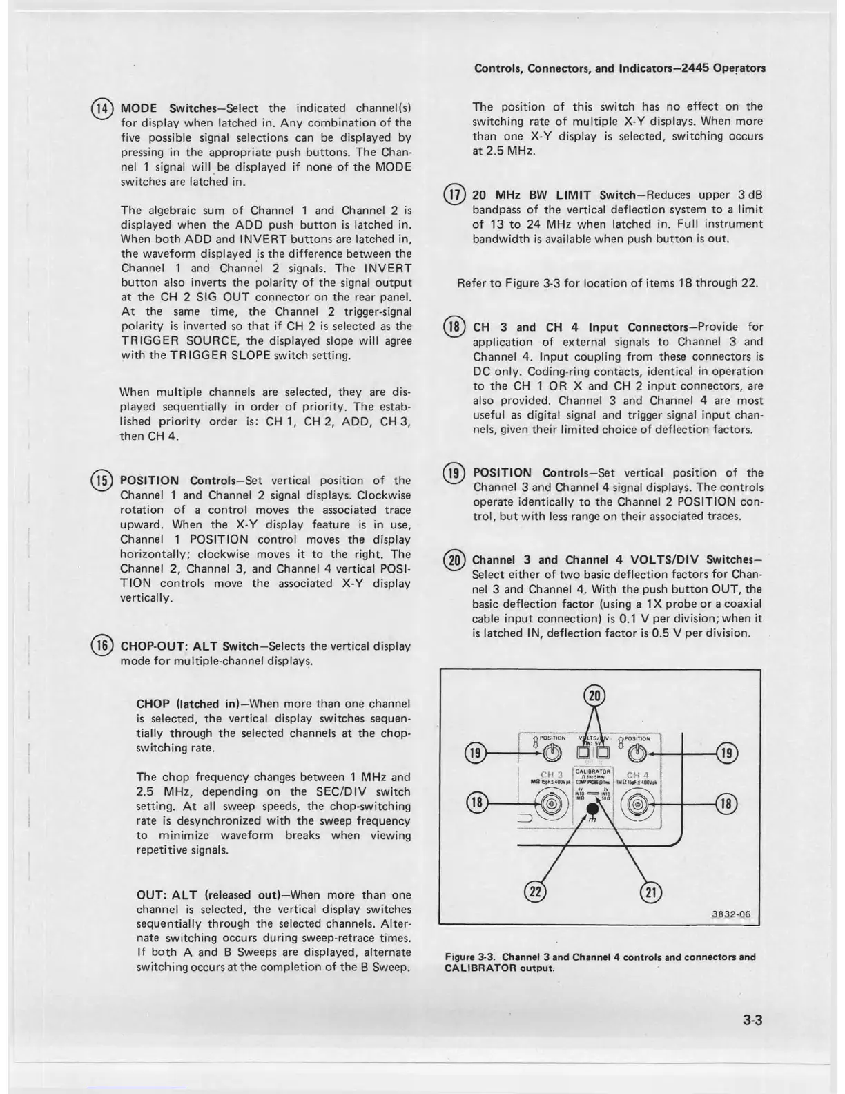
Refer to Figure 3-3 for location of items 18 through 22.
@ CH 3 and CH 4 Input Connectors—Provide for
application of external signals to Channel 3 and
Channel 4. Input coupling from these connectors is
DC only. Coding-ring contacts, identical in operation
to the CH 1 OR X and CH 2 input connectors, are
also provided. Channel 3 and Channel 4 are most
useful as digital signal and trigger signal input chan
nels, given their limited choice of deflection factors.
(T
5
) POSITION Controls—Set vertical position of the
Channel 1 and Channel 2 signal displays. Clockwise
rotation of a control moves the associated trace
upward. When the X-Y display feature is in use,
Channel 1 POSITION control moves the display
horizontally; clockwise moves it to the right. The
Channel 2, Channel 3, and Channel 4 vertical POSI
TION controls move the associated X-Y display
vertically.
(l6 ) CHOP-OUT: ALT Switch—Selects the vertical display
mode for multiple-channel displays.
CHOP (latched in)—When more than one channel
is selected, the vertical display switches sequen
tially through the selected channels at the chop
switching rate.
The chop frequency changes between 1 MHz and
2.5 MHz, depending on the SEC/DIV switch
setting. At all sweep speeds, the chop-switching
rate is desynchronized with the sweep frequency
to minimize waveform breaks when viewing
repetitive signals.
OUT: ALT (released out)—When more than one
channel is selected, the vertical display switches
sequentially through the selected channels. Alter
nate switching occurs during sweep-retrace times.
If both A and B Sweeps are displayed, alternate
switching occurs at the completion of the B Sweep.
(l9 ) POSITION Controls—Set vertical position of the
Channel 3 and Channel 4 signal displays. The controls
operate identically to the Channel 2 POSITION con
trol, but with less range on their associated traces.
(20) Channel 3 and Channel 4 VOLTS/DIV Switches—
Select either of two basic deflection factors for Chan
nel 3 and Channel 4. With the push button OUT, the
basic deflection factor (using a IX probe or a coaxial
cable input connection) is 0.1 V per division; when it
is latched IN, deflection factor is 0.5 V per division.
Figure 3-3. Channel 3 and Channel 4 controls and connectors and
CALIBRATOR output.
3-3