•
POSITION
TO
CENTERLINE
10-
........
~-.....--~------""-------~--
..........
-..+~-+
I
0
•...
MEASURE
AMPLITUDE
FROM A
TO
B (1738-16)2037-16
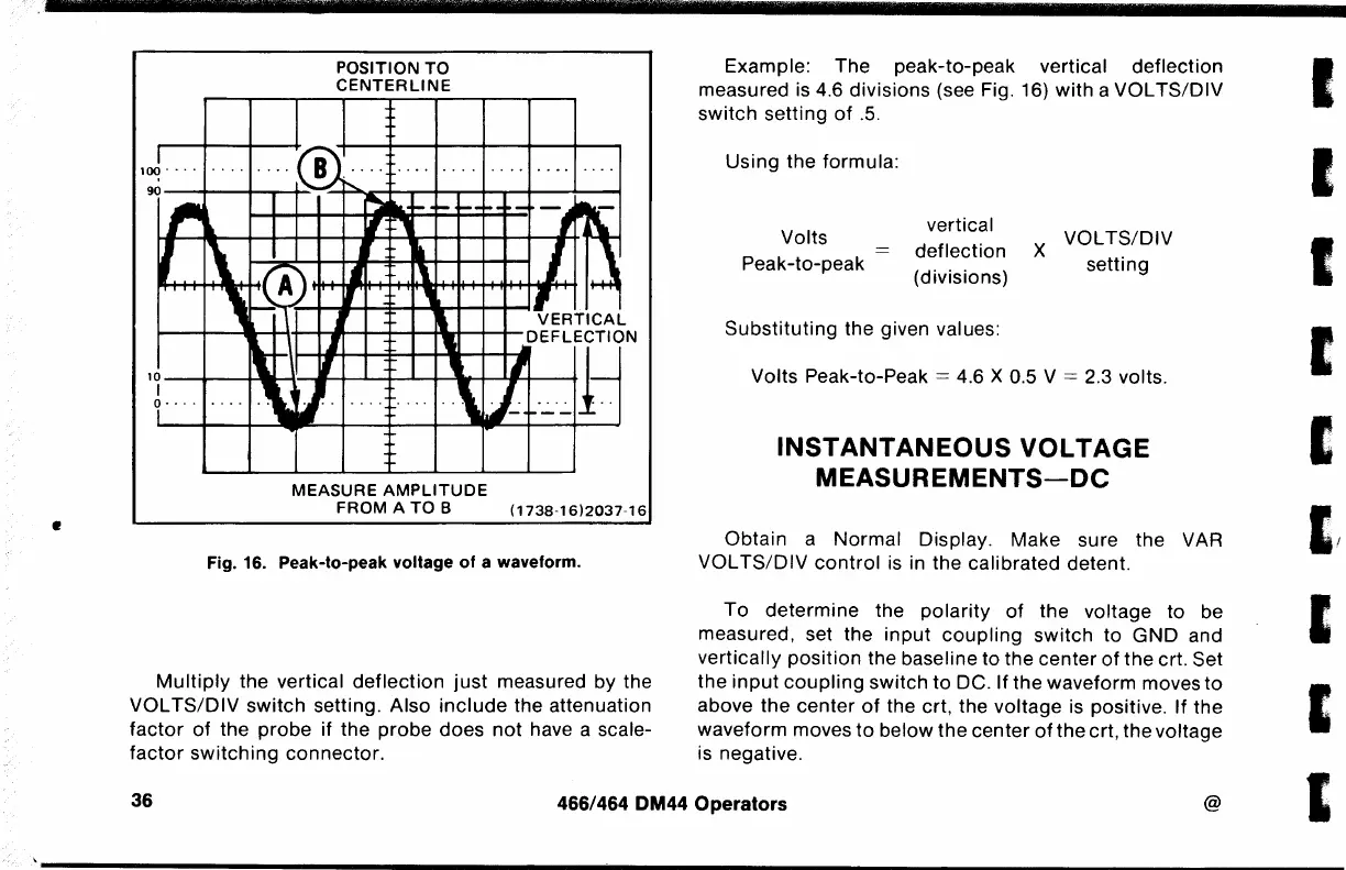
Fig. 16. Peak-to-peak voltage
of
a waveform.
Multiply
the vertical
deflection
just
measured by the
VOL
TS/DIV
switch
setting. Also
include
the attenuation
factor
of
the
probe
if the
probe
does
not
have a scale-
factor
switching
connector.
Example: The peak-to-peak vertical
deflection
measured is 4.6 divisions (see Fig. 16)
with
a VOL
TS/DIV
switch
setting
of
.5.
Using
the
formula:
Volts
Peak-to-peak
vertical
deflection
(divisions)
Substituting
the given values:
X
VOLTS/DIV
setting
Volts Peak-to-Peak
= 4.6 X 0.5 V = 2.3 volts.
INSTANTANEOUS
VOLTAGE
MEASUREMENTS-DC
Obtain
a
Normal
Display. Make sure the VAR
VOL
TS/DIV
control
is in the calibrated detent.
To
determine
the
polarity
of
the
voltage
to
be
measured, set the
input
coupling
switch
to
GND
and
vertically
position
the baseline to
the
center
of
the
crt. Set
the
input
coupling
switch
to
DC. If
the
waveform moves
to
above
the
center
of
the crt, the
voltage
is positive. If
the
waveform moves
to
below
the
center
of
the
crt, the voltage
is negative.
36
466/464 DM44
Operators
@
I
I
I
I
I
I